
XJ-6 L6-4.2L (1983)
Engine Control Module: Connector Views
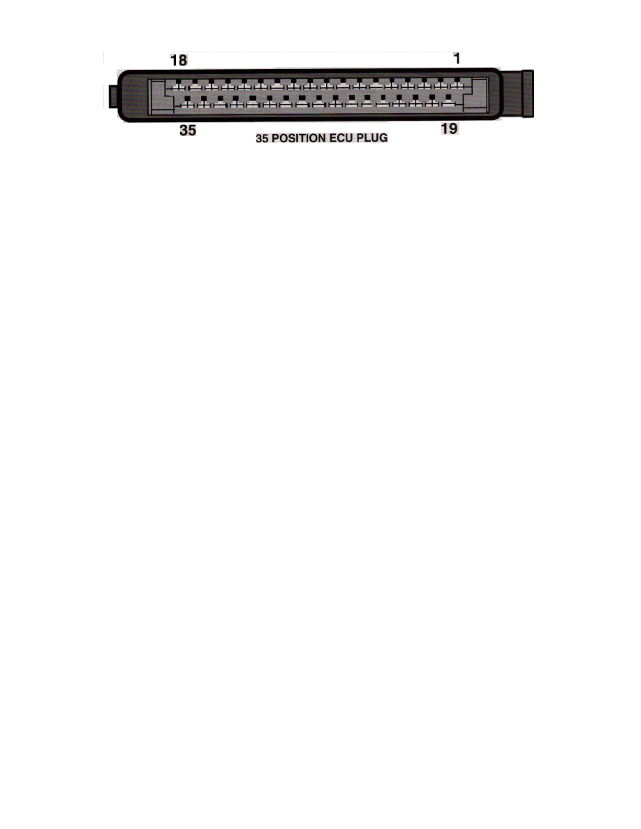
35 Position ECU Plug
CONNECTOR VIEW
SYSTEM
L-Jetronic
LOCATION
Behind glove box or in trunk.
TERMINAL ID
1 - Trigger input from coil(-)
2 - Closed throttle input
3 - Full Load throttle input
4 - Starter solenoid input
5 - Chassis ground
6 - Air flow sensor ground
7 - Air flow sensor load input
8 - Air flow sensor reference
9 - Air flow sensor supply
10 - Main relay power input
11 - N/A
12 - N/A
13 - Coolant temperature sensor input
14 - Injector 3 control
15 - Injector 6 control
16 - Chassis ground
17 - Chassis ground
18 - Throttle switch supply (common)
19 - N/A
20 - Fuel pump relay control
21 - N/A
22 - N/A
23 - O2 shield wire
24 - Oxygen sensor signal
25 - N/A
26 - N/A
27 - Air temperature sensor input
28 - N/A
29 - N/A
30 - Injector 2 control
31 - Injector 1 control
32 - Injector 4 control
33 - Injector 5 control
34 - Auxiliary air regulator ground
35 - Chassis ground