
XJ-6 L6-4.2L (1983)
Oxygen Sensor: Description and Operation
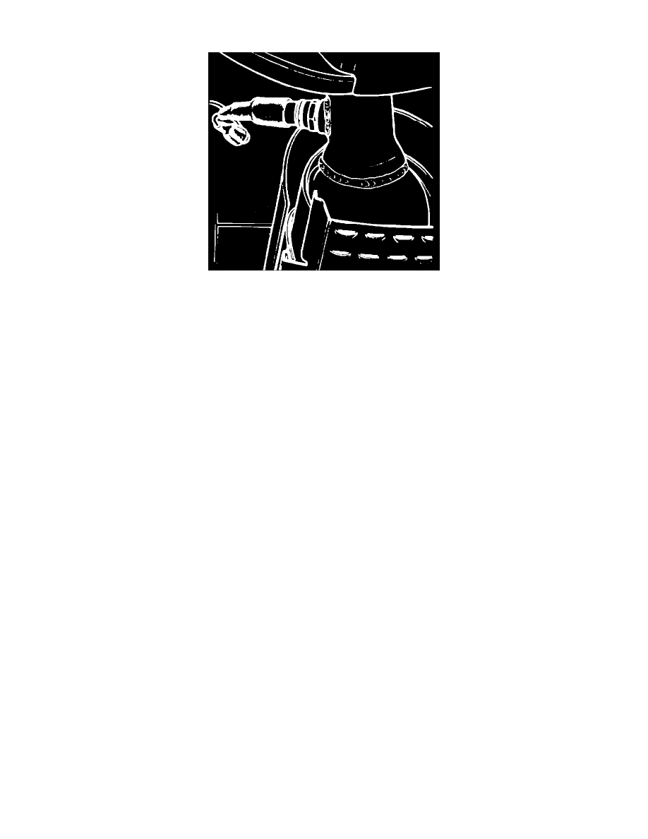
Fig. 6 Lambda sensor, typical installation.
One sensor is incorporated onto each branch of the exhaust system near the catalyst. The lambda sensors, Fig. 6, are internally coated with a thin
platinum layer which resists the exhaust gas. A ceramic layer protects the electrodes against corrosion and becomes a conductive layer to oxygen at
approximately 1112°F. A voltage is generated between the two surfaces when the concentration of oxygen inside the sensor differs from that outside of
the sensor. This voltage is transmitted to the E.C.U. which compares the transmitted voltage to a reference voltage for ideal combustion. The lambda
sensors are a closed loop type control system. If the lambda sensors become inoperative or become disconnected, the E.C.U. will continue to function as
an open loop system.