
XJ-S V12-5.3L (1982)
Piston: Service and Repair
Overhaul
- Remove pistons and connecting rods. Refer to Engine/Cylinder Block Assembly.
- Pistons are available in selective grades, identified by 'A' or 'B' stamped on the piston crown and the adjacent face of the cylinder liner.
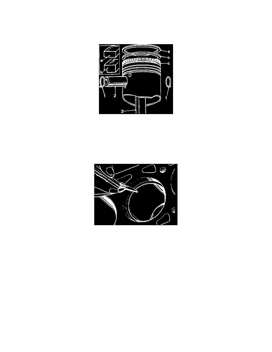
Piston And Rings
- Remove the wrist pin circlips (1).
- Remove the wrist pin (2) and withdraw the connecting rod (3).
- Remove the piston rings.
- The top and second rings both have tapered peripheries and the second ring is marked 'TOP' to be sure of correct fitting.
- The top ring has a chrome plated periphery and is 'Cargraph' coated. The 'Cargraph' coating is colored red and must not be removed.
- The bottom ring consists of an expander sandwiched between two rails, the assembly being held together by an adhesive.
Measuring Ring End Gap
- Insert the piston rings, one at a time, into the cylinder bores, be sure that they are square in the cylinders and check the gap using a feeler gauge.
Should be as follows:
Top compression ring gap ...................................................................................................................................................................... 0.360.51 mm
Second compression ring gap ............................................................................................................................................................... 0.25-0.38 mm
Oil control ring gap ............................................................................................................................................................................... 0.38-1.14 mm
- If the gap is insufficient, then a small flat file carborundum stone, or ring end grinder can be used on the butting ends of the ring. Be sure that after
filing no burrs remain.
NOTE: Be sure that the rings are not intermixed after they have been gapped.
- Measure the piston skirt clearance using a long feeler gauge. Insert the feeler gauge down the RH side of the cylinder bore, insert the correct piston
INVERTED into the bore (with the wrist pin parallel to the axis of the crankshaft). Push the piston down the cylinder until it reaches its tightest point
in the bore. At this point. withdraw the feeler gauge; a steady resistance should be felt.
- If the tolerances are outside those given below, the pistons must be replaced (as a set).
- Piston skirt clearance should be:
0.03 mm - 0.04 mm