
XJ-S V12-5.3L (1982)
Spark Plug: Service and Repair
Spark Plug Insert
-
Remove the appropriate cylinder head. Refer to CYLINDER HEAD / REMOVE AND REFIT.
-
After each cylinder head has been removed, JD 41 cylinder liner retainers, or equivalent, must be fitted to the engine. Failure to carry out this
operation will result in the Hylomar seal being broken, causing water leakage into the oil pan.
NOTE: Always support the cylinder heads on blocks of wood. This will prevent damage to the valves which, when open, protrude below the cylinder
head face.
-
Remove the spark plugs and exhaust manifolds from the cylinder head.
-
Gradually loosen each camshaft cap securing nut (two turns at a time) until the valve springs are fully relaxed.
-
Note the cap to carrier relationship.
-
Remove the nuts/washers and lift off the bearing caps.
-
Remove the camshaft.
-
Using a magnet, remove the cam followers.
-
Remove the camshaft carrier.
-
Remove the valve springs.
-
Retrieve the collars, cotters, and spring retaining plates.
-
Remove the valves, noting the relationship between valve and guide to be sure of correct pairing during reassembly.
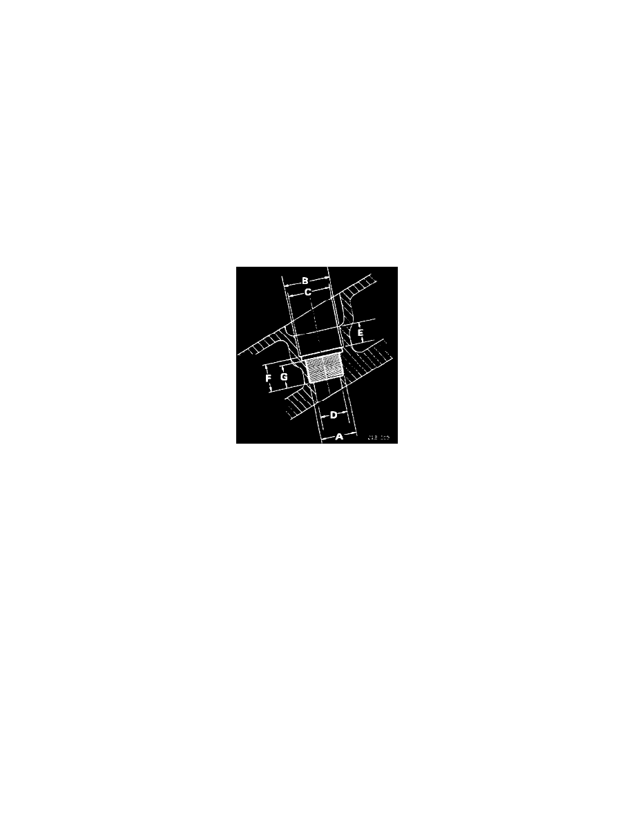
Spark Plug Insert Dimensions
-
Remove the seals from the inlet valve guides. Referring to image:
-
Bore out the stripped thread to 19.05 mm (0.750 in) diameter and tap out to 16 UNF - 2B (Dimension 'A').
-
Counterbore to 24.13 mm (O.95in) (Dimension 'B').
^
Dimension 'C' = 22.23 mm (O.875in).
^
Dimension 'D' = 14.22 mm-14.48 mm (O.560in - O.570in).
^
Dimension 'E' = 10.78 mm (O.425in).
^
Dimension 'F' = 15.75 mm (O.575in).
^
Dimension 'G' = 11.81 mm-11.94 mm (O.465in - O.470in).
-
Fit the screwed insert ensuring that it sits firmly at the bottom of the thread.
-
Drill and ream a 3.17 mm (0.125 in) diameter hole 2.83 mm (O.19in) deep, between the side of the insert and the head.
-
Drive in a locking pin and secure by peening the edge of the insert and the locking pin.