
Cherokee 2WD L4-126 2.1L DSL Turbo VIN B FI (1986)
Evaporative Emissions System: Description and Operation
This system is used to prevent fuel vapors emitted from the fuel tank and carburetor from escaping into the atmosphere. This is accomplished through
the use of a non-vented fuel tank, a special fuel filler cap, charcoal canister (some applications), vapor separators, check valves, vented carburetor, and
hoses necessary to connect these components together.
Fuel vapors are absorbed and stored in the charcoal canister until the engine is started. These vapors are then drawn either through the air cleaner
snorkel or through a ported vacuum port in the carburetor (depending on application) and burned along with the normal air/fuel mixture.
FUEL TANK
The fuel tank is equipped with an integral expansion area directly above the fuel to allow for normal fuel expansion. Some vehicles with this type of
fuel tank are equipped with a liquid check valve to prevent fuel from entering the vapor lines.
FUEL FILLER CAP
The fuel filler cap uses a two-way (vacuum and pressure) relief valve that is closed during normal operating conditions. The relief valve is calibrated
to open only when pressure in excess of .8 psi or vacuum in excess of .1 inch Hg develops in the fuel tank. When vacuum or pressure is relieved, the
valve returns to its normally closed position.
Some filler caps have a rollover check valve. This valve consists of a stainless steel ball in a plastic housing mounted on the fuel tank side of the cap.
Should the vehicle be overturned or tipped sufficiently, the steel ball drops into an orifice closing the vent to prevent fuel leakage. It is normal to
occasionally encounter an air pressure release when removing the fuel filler cap.
FUEL VAPOR STORAGE CANISTER (CHARCOAL CANISTER)
The fuel resistant nylon body of the canister contains activated charcoal granules which absorb and store fuel vapors until they are drawn into the
induction system to be burned along with the normal air fuel mixture. Outside air is drawn into the canister through a replaceable filter pad located at the
bottom of the canister.
The canister has a staged dual feature and four nipples. Two of the nipples are inlets, one for fuel tank vapor and the other for carburetor float bowl
vapor. The other two nipples are outlets, one is connected to intake manifold vacuum while the other is for carburetor ported vacuum. When the engine is
running, manifold vacuum causes fresh air to enter through the inlet filter in the canister and purge the stored vapor. When ported vacuum increases due
to increased throttle opening, the secondary purge circuit is opened and the canister is purged at a much higher rate.
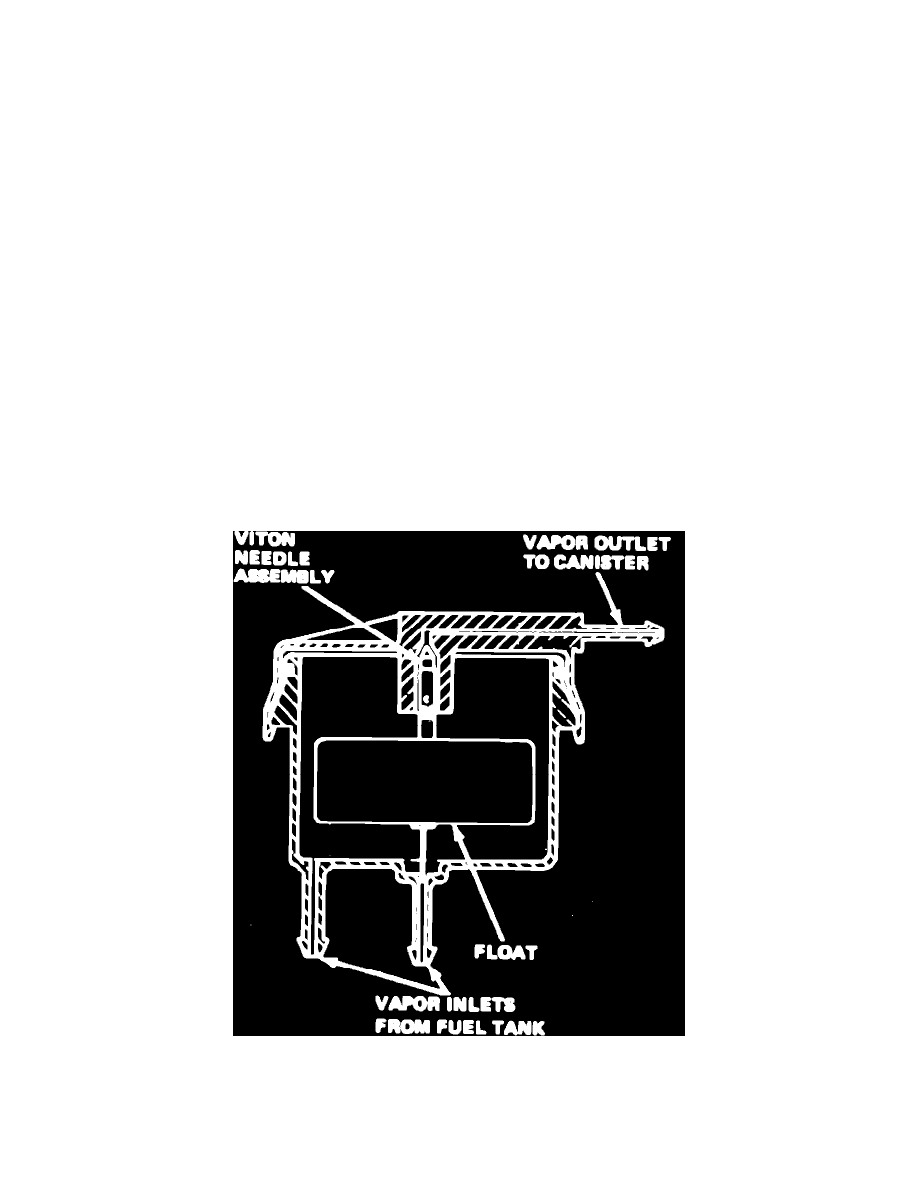
Fig. 13 Liquid check valve. Typical
LIQUID CHECK VALVE
This valve, Fig. 13, contains a float and Viton needle assembly. Should liquid fuel enter the check valve, the float will rise and force the needle
upward closing the vent passage and preventing fuel from flowing through the valve. Two different design valves are used, one picks up vapors from the