
Cherokee 2WD L4-126 2.1L DSL Turbo VIN B FI (1986)
The EGR valve, Figs. 18 and 19, is mounted on a machined surface at the rear of the intake manifold on V8 engines, on the side of the intake
manifold on six cylinder engines and on a space-plate beneath the carburetor on four cylinder engines. The valve used with an automatic transmission is
calibrated differently than the valve used with a manual transmission.
The valve is held in a normally closed position by a coiled spring located above the diaphragm. A special fitting is provided at the carburetor to route
ported (above throttle) vacuum through hose connections to a fitting on the valve which is located above the diaphragm. A passage in the intake manifold
directs exhaust gas from the exhaust crossover passage or from below the riser area to the EGR valve. When the diaphragm is actuated by vacuum, the
valve opens and meters exhaust gas through another passage in the intake manifold to the floor of the manifold below the carburetor.
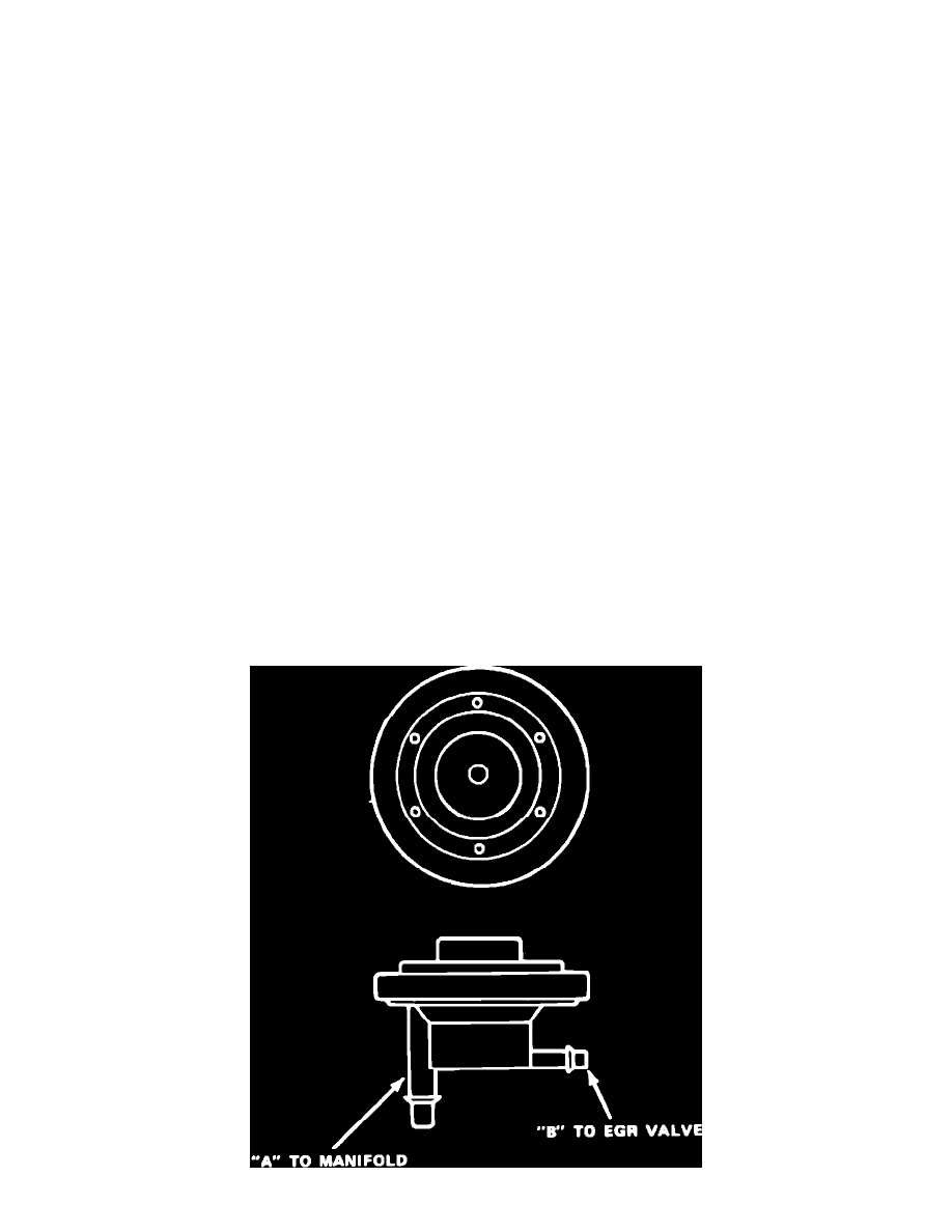
The EGR valve with an integral exhaust back pressure sensor, Fig. 18, combines the functions of the EGR valve and separate back pressure sensor
into a single unit. This unit is calibrated by the use of selective diaphragm spring loads and flow control orifices. The exhaust gas flow is controlled by a
moveable pintle. When no vacuum is applied to the diaphragm, the pintle is held against its seat by spring tension, confining exhaust gases to the exhaust
manifold. When vacuum is applied to the diaphragm, the pintle is forced from its seat, however, this cannot occur if the vacuum bleed valve in the power
diaphragm is opened. Exhaust gas back pressure from inside the exhaust manifold flows through the hollow pintle stem into the control diaphragm
chamber. If this pressure is enough to overcome the control spring tension, the control diaphragm moves against its bleed valve. Full vacuum is now
applied to the power diaphragm and the pintle moves, allowing exhaust gas to flow to the intake manifold. If the exhaust back pressure drops enough, the
control diaphragm moves away from the bleed valve and the pintle returns to its seat.
COOLANT TEMPERATURE OVERRIDE SWITCH
This switch is located at the coolant passage of the intake manifold (adjacent to oil filler tube) on a V8 engine, at the left side of the engine block
(formerly the drain plug location) on a six cylinder engine or in coolant passage at right rear of cylinder head on four cylinder engines. The outer part of
the switch is open and not used. The inner port is connected by a hose to the EGR fitting at the carburetor. The outer port is connected to the EGR valve,
or to the TVS on four cylinders.
When the coolant temperature is below 115° F (160° F on some vehicles), the center port of the switch is closed and no vacuum signal is applied to
the EGR valve, therefore, no exhaust gas will flow through the valve. When the coolant temperature reaches 115° F (160° F on some vehicles), both the
center and inner port of the switch are open and a vacuum signal is applied to the EGR valve. However, the vacuum signal to the EGR valve is subject to
regulation by low and high temperature signal modulators.
LOW TEMPERATURE VACUUM SIGNAL MODULATOR
This unit is located at the left side of the front upper crossmember, just ahead of the radiator, on the same mounting bracket as the TCS ambient
temperature override switch and is connected to the EGR vacuum signal hose. The modulator is open when ambient temperatures are below 60° F. This
causes a weakened vacuum signal to the EGR valve and a resultant decrease in the amount of exhaust gas being recirculated.
HIGH TEMPERATURE VACUUM SIGNAL MODULATOR
This unit is located at the rear of the engine compartment and is connected to the EGR vacuum signal hose. The modulator opens when the underhood
air temperature reaches 115° F and causes a weakened vacuum signal to the EGR valve. As a result, the amount of exhaust gas being recirculated is
decreased.