
Cherokee 2WD L4-150 2.5L VIN H TBI (1988)
Fuel Pump Relay: Testing and Inspection
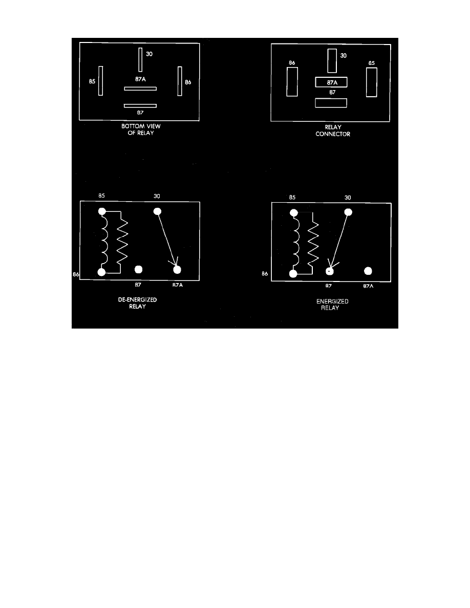
Relay Terminal Identification
FUEL PUMP RELAY TERMINAL IDENTIFICATION
The following is a list of the terminal numbers, with circuit codes, and color codes, and their function:
Circuit No. Terminal No.
Color Code
Description
10
30
Red
Has battery input voltage supplied through fusible link.
F22
87
Orange
Connected to 10 circuit (terminal 30) in the energized position, supplies output voltage to fuel pump,
EGR/EVAP solenoid, and fuel injectors.
F17
86
Orange
Connected to the Electronic Control Unit (ECU), which provides input voltage to the relay.
11
85
Yellow
Connected to the ECU, and grounded by the ECU when distributor signal is present.
N/A
87A
N/A
Not used in these applications.
FUEL PUMP RELAY TEST
NOTE: The Fuel Pump relay operation may be tested with the use of the DRB II scanner or equivalent. Refer to COMPUTERIZED ENGINE
CONTROLS/DIAGNOSIS AND TESTING for procedure. If no scanner is available proceed with the following test.
1.
Connect a voltmeter to the 10 (terminal 30) wire at the fuel pump relay connector. Check for battery voltage. If no voltage is present, check
fusible links and supply voltage from the battery. If voltage is present proceed to step 2.
2.
Connect the voltmeter to the F22 (terminal 87) wire at the fuel pump relay connector. Turn the ignition key to the START position and crank the
engine. If output voltage is present during cranking, the fuel pump relay is functioning normally and no further testing of the fuel pump relay is
necessary. If no voltage is present at the F22 wire, proceed to step 3.
3.
Connect the voltmeter to the F17 (terminal 86) wire at the fuel pump relay connector. Turn the ignition key to the RUN position. Input voltage