
Cherokee 2WD L4-150 2.5L VIN H TBI (1988)
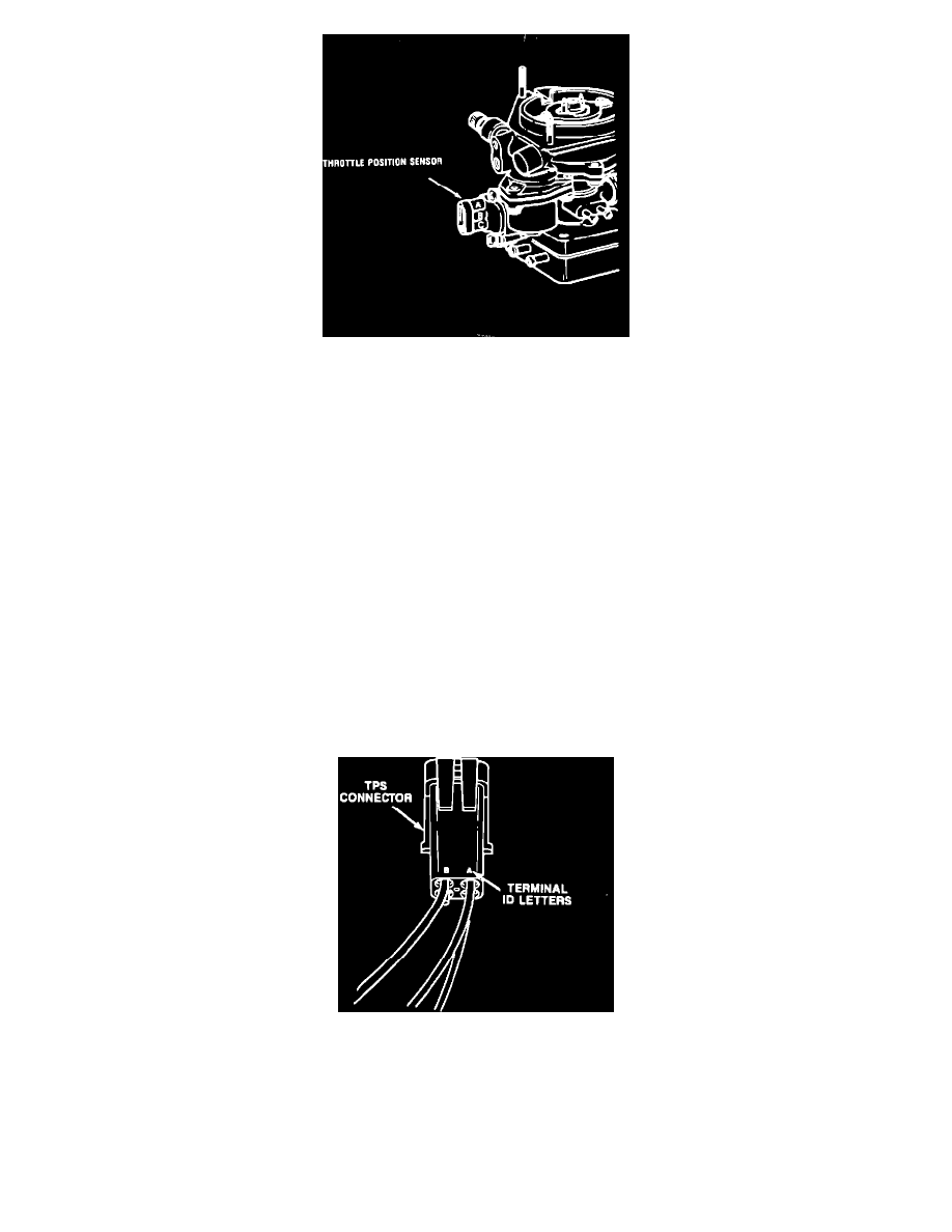
FIGURE 3
2.
Do not remove the electrical connector from the TPS. Connect the positive lead of the voltmeter to terminal C and the negative lead to terminal B
of the TPS connector (Figure 3). The leads must be inserted through the back of the connector to make contact with the terminals. The terminal
identification letters are molded into the connector.
3.
With the throttle plate held in the wide open throttle (W.O.T.) position, note the "input" voltage. It should be approximately 5.0 volts.
4.
Remove the voltmeter positive lead from terminal C and connect it to terminal A. The "output" voltage should be 4.6 to 4.7 volts. If this is not the
case, continue with this procedure.
5.
Adjust output voltage as follows: with the voltmeter leads still attached, carefully loosen the sensor mounting screws and slowly rotate the sensor
until the output reading is 4.6-4.7 volts with the throttle wide open. Then, tighten the sensor mounting screws securely. Be sure not to disturb the
sensor's position while tightening the screws. Adjustment is now complete.
TPS Adjustment Procedure - 2.5L Engine With Automatic Transmission
NOTE:
THE TPS FOR THE FUEL INJECTION SYSTEM IS INTEGRAL WITH THE TPS FOR THE AUTOMATIC TRANSMISSION.
THEREFORE, ADJUSTING THE TPS CORRECTLY FOR THE TRANSMISSION WILL AUTOMATICALLY ADJUST THE
"FUEL INJECTION" TPS PROPERLY. THE PREFERRED METHOD FOR ADJUSTING THE TRANSMISSION TPS IS USING
THE MS 1700 TESTER IN THE "AUTO TRANS TEST" MODE AND FOLLOWING THE INSTRUCTIONS THAT THE TESTER
DISPLAYS. HOWEVER, THE TPS CAN BE ADJUSTED USING A VOLTMETER AND THE FOLLOWING PROCEDURE.
1.
Turn the ignition switch to the "ON" position.
FIGURE 4
2.
There are two wire harness connectors attached to the TPS. Input/output voltage is checked at the SQUARE, FOUR-TERMINAL connector
(Figure 4). The terminals are identified by the letters A, B, C, and D molded into the connector.
3.
Do not unplug the connector. The voltmeter leads must be inserted through the back of the connector to make contact with the terminals. Connect
the positive lead to terminal A and the negative lead to terminal D.
4.
With the throttle plate in the wide open throttle (W.O.T.) position, note the "input" voltage. It should be approximately 5.0 volts.