
Cherokee 2WD L4-150 2.5L VIN H TBI (1988)
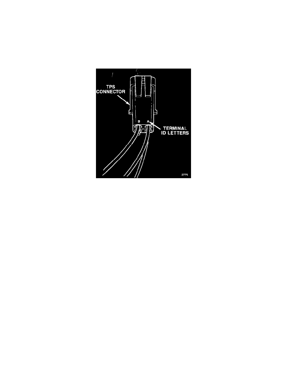
FIGURE 5
TPS Connector
TPS input/output voltage is checked at the square, four-terminal, two-piece connector (3) (Fig. 5).
If diagnosis indicates a loose or corroded connection, release the lock tab and separate the two halves of the connector. Inspect and clean the connector
terminals if dirty or corroded.
Be sure the connector halves are fully seated before engaging the lock tab. This is necessary to ensure a good connection.
FIGURE 6
Testing TPS Operation
A voltmeter is used to test the TPS. Operation is checked by measuring input and output voltage at the TPS connector terminals.
The connector terminals are identified by the letters A, B, C, D molded into the back of the connector (Fig. 6).
Testing Input Voltage
1.
Turn the ignition key to the On position.
2.
Connect the voltmeter negative lead to terminal D.
NOTE:
To contact the connector terminal, insert the voltmeter test lead from the back of the connector. Insert the lead between the wire and rubber
seal to contact the terminal.
3.
Connect the voltmeter positive lead to terminal A.
4.
Close the throttle plate completely. Be sure the throttle lever is seated against the idle stop.
5.
Note input voltage. Voltage at terminals A and D should be approximately 5.0 volts on both four and six-cylinder engines.
6.
Leave the voltmeter leads in place and proceed to the output voltage test.
Testing Output Voltage
1.
Remove the voltmeter positive lead from terminal A and connect it to terminal B.
2.
On four-cylinder engines, move the throttle plate to the wide open position and note output voltage. Output voltage should be 4% of input voltage
(approximately 0.2 volts).
3.
On six-cylinder engines, hold the throttle plate closed and note output voltage. Voltage should be 82% of input voltage (approximately 4.2 volts).
4.
If output voltage is not within the specified range, leave the voltmeter connected and proceed to TPS adjustment.