
Cherokee 2WD L4-150 2.5L VIN P MFI (1991)
Fuel Pump Ballast Bypass Relay: Testing and Inspection
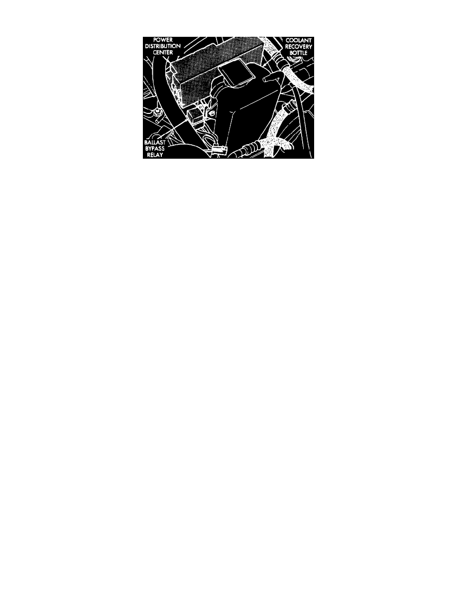
Ballast Bypass Relay
BALLAST BYPASS RELAY TERMINAL IDENTIFICATION
The following is a list of the terminal numbers, with circuit codes, and color codes, and their function:
Circuit No. Terminal No.
Color Code
Description
A141
1
Dk.Gn./BK
Has battery input voltage supplied from the fuel pump relay, and supplies voltage to the oxygen sensor.
K37
2
DB/RD
This circuit is the ground circuit, for the ballast bypass relay, to the SBEC II.
A241
3
DG/TN
This circuit bypasses the fuel pump ballast resistor, and provides voltage to the fuel pump.
F12
5
DB/WT.
This circuit provides battery input voltage to the fuel pump ballast bypass relay through fuse F6.
BALLAST BYPASS RELAY TEST
NOTE: The ballast bypass relay operation may be tested with the use of the DRB II scanner or equivalent.
If no scanner is available proceed with the following test.
NOTE: The fuel system wiring diagrams should be used in conjunction with the following test to correctly diagnose the problem.
1.
Pull the bypass relay out of its connector and connect a voltmeter to the A141 wire (terminal 1). With the engine running, or for 2 to 3 seconds
while starting, battery voltage should be present at this terminal. If no voltage is present, refer to FUEL PUMP RELAY TEST. If voltage is
present proceed to step 2.
2.
Connect the voltmeter to the A241 (terminal 3) wire at the ballast bypass relay connector. Turn the ignition key to the START position and crank
the engine. If output voltage is present during cranking, or wide open throttle, the ballast bypass relay is functioning normally and no further
testing of the ballast bypass relay is necessary. If no voltage is present at the A241 wire, proceed to step 3.
3.
Connect the voltmeter to the K37 wire (terminal 2) at the ballast bypass relay connector. Turn the ignition key to the RUN position, wait for 5
seconds, and check for voltage. If voltage is present, go to step 4. If no voltage is present, pull the ballast bypass relay out of its connector and
connect an ohmmeter across the F12 and K37 terminals of the relay, and check for continuity. If continuity exists, repair the F12 circuit between
the bypass relay and fuse F6. If no continuity exists, replace the ballast bypass relay and retest its operation.
4.
Disconnect the 60-Way SBEC II connector, and connect an ohmmeter between the K37 wire (terminal 2) of the ballast bypass relay connector and
pin No. 37 at the SBEC II, and check for continuity. If continuity exists, the problem is computer related.
If no continuity exists, repair open in wire and retest the operation of the ballast bypass relay.
NOTE: If the there is continuity between circuits F12 and K37, and voltage is not present at K37 (there is voltage at the bypass relay on circuit F12 with
circuit F12 disconnected from ballast bypass relay), then the SBEC II may be grounding the ballast bypass relay continuously through circuit K37. See:
Fuel Pump Ballast Resistor/Testing and Inspection