
Cherokee 2WD L4-150 2.5L VIN P MFI (1991)
Fuel Pump Relay: Testing and Inspection
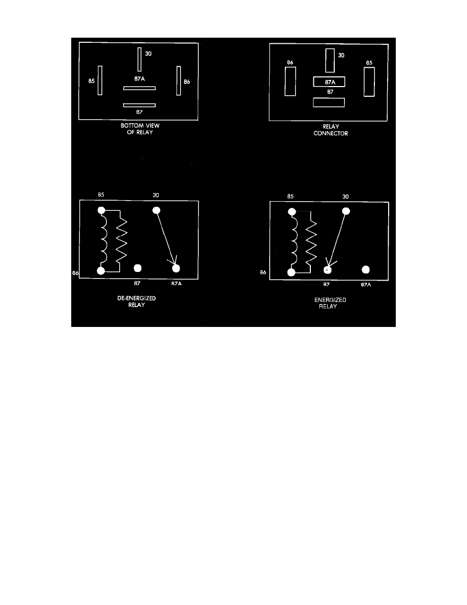
Relay Terminal Identification
FUEL PUMP RELAY TERMINAL IDENTIFICATION
The following is a list of the terminal numbers, with circuit codes, and color codes, and their function:
Circuit No. Terminal No.
Color Code
Description
A14
30
Red
Has battery input voltage supplied through fusible link.
A141
87
DG/BK
Connected to A14 circuit (terminal 30) in the energized position, supplies output voltage to the ballast
bypass relay and the fuel pump ballast resistor.
A21
86
DB
This circuit provides voltage to the ASD relay and the fuel pump relay, from the SBEC II.
K51
85
DG/YL
This circuit is the ground circuit for both the fuel pump relay and the ASD relay. This circuit connects to
the electromagnet (diode) in the SBEC II. The SBEC II grounds this circuit when a distributor signal is
present.
N/A
87A
N/A
Not used in these applications.
FUEL PUMP RELAY TEST
NOTE: The fuel pump relay operation may be tested with the use of the DRB II scanner or equivalent.
If no scanner is available proceed with the following test.
NOTE: The fuel system wiring diagrams should be used in conjunction with the following test to correctly diagnose the problem.
1.
Connect a voltmeter to the A14 (terminal 30) wire at the fuel pump relay connector. Check for battery voltage. If no voltage is present, check