
Cherokee 2WD L4-150 2.5L VIN P MFI (1991)
Crankshaft Position Sensor: Description and Operation
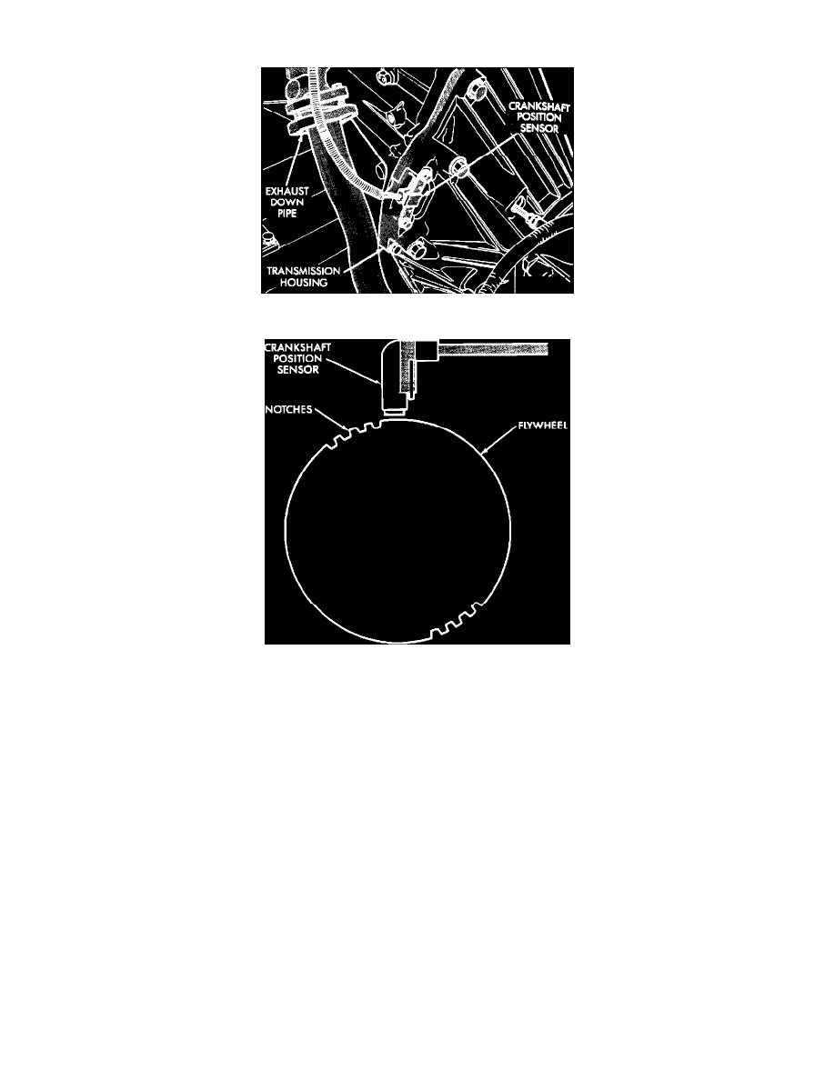
Crankshaft Position (CKP) Sensor 2.5L
Crankshaft Position (CKP) Sensor Operation
This sensor is located on the bellhousing of the transmission, and is used to send voltage signals, relating to engine speed and piston position, to the
SBEC II. The SBEC II converts the signals, rate of change of crankshaft angle and crankshaft angle, into engine RPM and piston position respectively.
It has a magnetic core inside it that creates a voltage output when a conductor passes through the magnetic flux that it emits. The flywheel has a large
drive plate with two groups of four large trigger teeth (180 degrees apart).
When the notches pass under the magnetic core in the sensor, they move through the lines of magnetic flux emitted by the sensor. As these teeth
approach the lines of magnetic flux, they cause the magnetic field to concentrate or intensify, and as the teeth pass through the magnetic field, the
magnetic field collapses. This concentration and collapsing of the magnetic field causes voltage spikes in the sensors pick-up winding. The engine
controller sees every one of these voltage spikes and counts them as they pass the sensor. For each engine revolution, there are two groups of four
pulses.
The trailing edge of the fourth notch is 4 degrees before top dead center of its corresponding cylinder. Through the use of the Crankshaft Position
Sensor (CPS) and other sensor inputs the engine controller controls (advances or retards) the ignition timing. The engine will not operate if the engine
controller does not receive a signal from the Crankshaft Position Sensor (CPS).