
Cherokee 2WD L6-242 4.0L VIN M FI (1987)
Starter Relay: Description and Operation
ECU Input Component Description
Coolant Temperature Sensor (CTS)
The coolant temperature sensor, which is located on the left hand side of the cylinder block below the exhaust manifold, provides engine temperature
input to the Electronic Control Unit. The ECU will use the inputs from the CTS when coolant temperature are cold, to enrich the air/fuel mixture,
control engine warm-up idle speed, increase ignition advance and inhibit the EGR system.
Manifold Air Temperature (MAT) Sensor
The manifold air temperature sensor, which is located in the intake manifold, provides an air temperature input to the ECU. The ECU in turn will
compensate for air density changes during high temperature operation.
Manifold Absolute Pressure (MAP) Sensor
The manifold absolute pressure sensor is located on the firewall behind the engine. A hose from the intake manifold provides the input pressure for the
sensor. The sensor will react to absolute pressure in the intake manifold and will provide an input voltage to the ECU. The signal from the MAP sensor
supplies the ECU with mixture density information and ambient barometric pressure information.
Oxygen Sensor
The Exhaust Gas Oxygen Sensor is NOT a voltage generating device. This sensor detects exhaust oxygen content by acting as a variable resistor. The
exhaust gas oxygen sensor provides the ECU with a feedback signal. By measuring the amount of oxygen in the exhaust gases, the oxygen sensor tells
the ECU how well its output signals are properly controlling the air/fuel ratio. Based on this feedback, the ECU can adjust its outputs to produce the
correct air/fuel ratio.
Variations in the voltage signal from the oxygen sensor serve as air/fuel ratio indicators, changes occur because the oxygen sensor acts as a variable
resistor. When oxygen content is low (rich mixture), the voltage signal will be less than 2.5 volts. A lean mixture (high oxygen content), the voltage
signal is above 2.5 volts.
The resistance element in the oxygen sensor is a small, titania semiconductor. The titania oxygen sensor must be connected into a voltage network. A 5
volt reference is applied to a fixed resistor (located in the ECU) that is wired in series with the oxygen sensor. The ECU then checks the voltage between
the fixed resistor and the oxygen sensor and then relates the voltage to oxygen content.
The oxygen sensor contains a heater in the sensor housing. The heater is a ceramic, resistance-type element that operates on 12 volts supplied through a
relay controlled by the ECU. The heater is needed to maintain the titania semiconductor at its operational temperature of approximately 1475 degrees F.
(850 degrees C.)
The oxygen sensor heater relay is controlled by the ECU. When the ECU determines high exhaust gas rates and exhaust gas oxygen sensor heating is
no longer required, the ECU completes the relay coil ground circuit. When the ground circuit is complete, the relay contacts open, and the exhaust gas
oxygen sensor heater is disabled.
Knock Sensor
This sensor is located at the lower left hand side of the cylinder block, just above the oil pan. This sensor provides an input to the ECU when
detonation is encountered during engine operation. The ECU will retard ignition timing when the input signal from the knock sensor indicates engine
detonation.
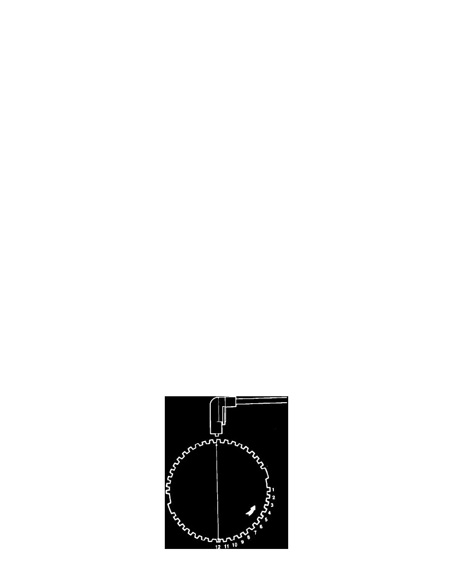
Fig. 1 Flywheel tooth identification