
Cherokee 2WD L6-4.0L VIN S (1998)
Manifold Pressure/Vacuum Sensor: Testing and Inspection
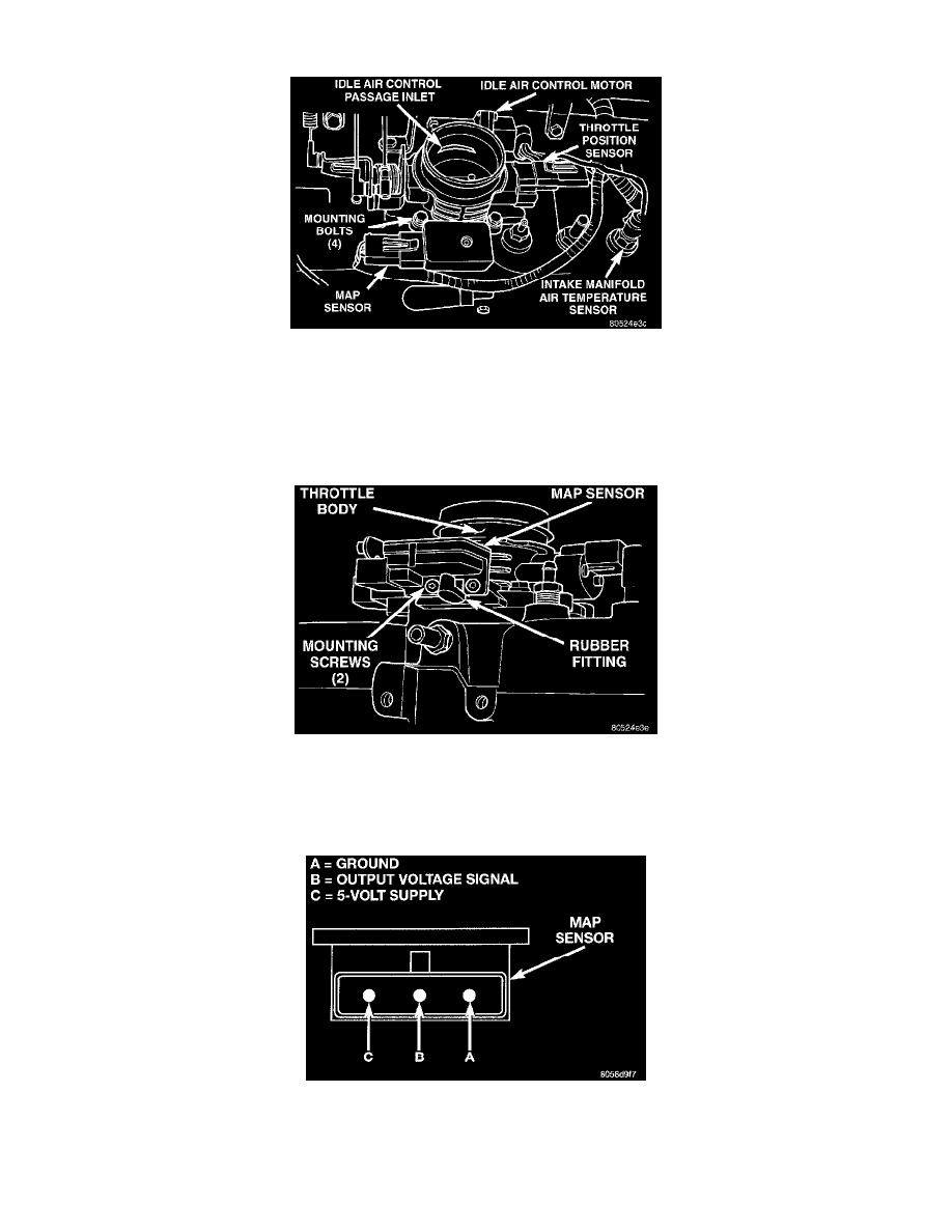
Fig 25 Sensor Location-Typical
To perform a complete test of MAP sensor (Fig. 25) and its circuitry, refer to Powertrain Management/Computers and Control
Systems/Testing and Inspection.
See: Testing and Inspection
To test the MAP sensor only, refer to the following:
Fig. 26 Rubber L-Shaped Fitting-Map Sensor-to-Throttle Body
1. Inspect the rubber L-shaped fitting from the MAP sensor to the throttle body (Fig. 26). Repair as necessary.
CAUTION: When testing the MAP sensor, be sure that the harness wires are not damaged by the test meter probes.
Fig. 27 Map Sensor Connector Terminals-Typical
2. Test the MAP sensor output voltage at the MAP sensor connector between terminals A and B (Fig. 27). With the ignition switch ON and the
engine OFF, output voltage should be 4-to-5 volts. The voltage should drop to 1.5-to-2.1 volts with a hot, neutral idle speed condition.
3. Test powertrain control module (PCM) cavity A-27 for the same voltage described above to verify the wire harness condition. Repair as necessary