
Cherokee 4WD L6-242 4.0L VIN S MFI (1992)
Manifold Pressure/Vacuum Sensor: Testing and Inspection
MAP Sensor Test
PROCEDURE
1.
Inspect the MAP sensor vacuum hose connections at the throttle body and sensor. Repair as necessary.
CAUTION: When testing the MAP sensor, ensure that the harness wires are not damaged by the test meter probes.
2.
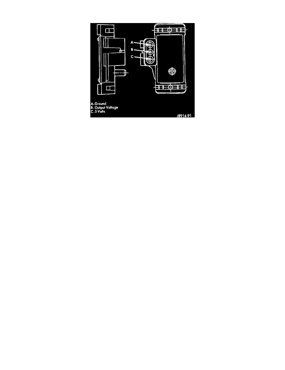
Test the MAP sensor output voltage at the MAP sensor connector terminal B (as marked on the sensor body).
^
This is done with the ignition switch ON and the engine OFF. Output voltage should be 4-to-5 volts. The voltage should drop to 1.5-to-2.1
volts with a hot, neutral idle speed condition.
3.
Test engine controller (terminal 5) for the same voltage described above to verify the wire harness condition. Repair as necessary.
4.
Test MAP sensor supply voltage at sensor connector (terminal C) with the ignition ON.
^
The voltage should be approximately 5 volts (±0.5V). Five volts (±0.5V) should also be at terminal 6 of the engine controller wire harness
connector. Repair or replace the wire harness as necessary.
5.
Test the MAP sensor ground circuit at sensor connector (terminal A) and engine controller connector (terminal 4). Repair the wire harness if
necessary.
6.
Test the MAP sensor ground circuit at the engine controller connector between terminal 4 and terminal 11 with an ohmmeter.
^
If the ohmmeter indicates an open circuit, inspect for a defective sensor ground connection. This connection is located on the right side of the
cylinder block at the oil dipstick tube mounting stud. If the ground connection is good, replace the engine controller. If terminal 4 has a short
circuit to 12 volts, correct this condition before replacing the engine controller.