
Cherokee 4WD L6-4.0L VIN S (1998)
Power Door Lock Control Module: Testing and Inspection
If the power lock system is inoperative with either front door power lock switch, test the Passenger Door Module (PDM). If the power lock system is
inoperative with only the driver side front door power lock switch, test the Driver Door Module (DDM).
Driver Door Module
The only function of the Driver Door Module (DDM) in the power lock system is to provide a Lock or Unlock signal to the power lock system
control circuitry contained within the Passenger Door Module (PDM). The DDM signals the PDM by providing a hard-wired ground path through
the DDM ground circuit and the driver side power lock switch contacts to the lock request or unlock request terminals of the PDM. The DDM
power lock switch function can be tested as follows:
1. Disconnect and isolate the battery negative cable. Remove the driver side front door trim panel and unplug the 12-way DDM wire harness
connector (C-2) from the DDM. Check for continuity between the ground circuit cavity of the 12-way DDM wire harness connector and a
good ground. There should be continuity. If OK, go to Step 2. If not OK, repair the open circuit to ground as required.
2. If the problem being diagnosed is inoperative power lock switch illumination, proceed as follows. If the problem is not power lock switch
illumination, go to Step 4. Connect the battery negative cable. Turn the ignition switch to the Accessory or On positions. Check for battery
voltage at both sides of the power window circuit breaker in the junction block. If OK, go to Step 3. If not OK, replace the faulty circuit
breaker.
3. With the ignition switch still in the On or Accessory position, check for battery voltage at the fused ignition switch output circuit cavity of the
12-way DDM wire harness connector. If OK, replace the faulty DDM. If not OK, repair the open circuit to the junction block as required.
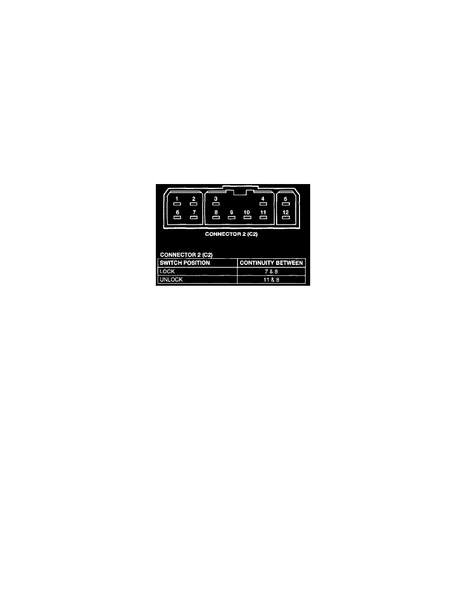
DDM Power Lock Switch Continuity
4. Test the power lock switch continuity through the DDM 12-way wire harness connector receptacle. See the DDM Power Lock Switch
Continuity chart to determine if the continuity is correct in the Lock and Unlock switch positions. If OK, repair the lock request circuit and/or
the unlock request circuit between the DDM and the PDM as required. If not OK, replace the faulty DDM.
Passenger Door Module
The Passenger Door Module (PDM) contains the passenger side front door power lock switch and the power lock system control circuitry. In its
role as a power lock switch, it provides the power lock system control circuitry with a ground path through the PDM ground circuit and the driver
side power lock switch contacts to indicate a lock request or unlock request.
In its role as the power lock control module, the PDM receives inputs from the battery the ignition switch, the DDM, the driver door ajar switch,
the key-in ignition switch, and the headlamp switch. It also receives a hard-wired input from the RKE receiver, if the vehicle is so equipped. In
response to these inputs, the PDM sends the proper outputs to control the power lock motors through its integral power lock and unlock relays.
The PDM power lock system functions can be tested as outlined below. If the power lock system operates, but the RKE system lock and/or unlock
functions are inoperative, see the diagnosis for the Body and Frame/Locks/Keyless Entry/Remote Keyless Entry Transmitter.
1. Check the fuse in the junction block. If OK, go to Step 2. If not OK, repair the shorted circuit or component as required and replace the faulty
fuse.
2. Disconnect and isolate the battery negative cable. Remove the passenger side front door trim panel and unplug the 8-way PDM wire harness
connector (C-1) from the PDM. Check for continuity between the ground circuit cavity of the 8-way PDM wire harness connector and a good
ground. There should be continuity. If OK, go to Step 3. If not OK, repair the open circuit to ground as required.
3. If the problem being diagnosed is inoperative power lock switch illumination, proceed as follows. If the problem is not power lock switch
illumination, go to Step 5. Connect the battery negative cable. Turn the ignition switch to the Accessory or On positions. Check for battery
voltage at both sides of the power window circuit breaker in the junction block. If OK, go to Step 4. If not OK, replace the faulty circuit
breaker.
4. With the ignition switch still in the Accessory or On positions, check for battery voltage at the fused ignition switch output circuit cavity of the
8-way PDM wire harness connector. If OK, replace the faulty PDM. If not OK, repair the open circuit to the junction block as required.
5. If the problem being diagnosed is an inoperative door lock inhibit feature or a power lock system that responds to an Unlock command, but not
a Lock command, proceed as follows. Otherwise, go to Step 7. With the driver side front door closed, check for continuity between the door
ajar/key-in circuit cavity of the 8-way PDM wire harness connector and a good ground. There should be no continuity. If OK, go to Step 6. If
not OK, repair the shorted door ajar and/or key-in ignition circuits as required. Refer to Instrument Panel, Gauges and Warning
Indicators/Audible Warning Device/Chime/Buzzer Warning Systems for more information.
6. Open the driver side front door with the key in the ignition switch or with the headlamp switch in the On position. Check for continuity
between the door ajar/key-in circuit cavity of the 8-way PDM wire harness connector and a good ground. There should be continuity If OK, go