
Cherokee 4WD L6-4.0L VIN S (1998)
Crankshaft Main Bearing: Service and Repair
Measuring Bearing Clearance
CRANKSHAFT MAIN BEARING CLEARANCE
Engine crankshaft bearing clearances can be determined by use of Plastigage, or equivalent. The following is the recommended procedures for the use
of Plastigage:
1. Remove oil film from surface to be checked. Plastigage is soluble in oil.
2. The total clearance of the main bearings can only be determined by removing the weight of the crankshaft. This can be accomplished by either of
two methods:
Method-1 (Preferred)
Shim the bearings adjacent to the bearing to be checked. This will remove the clearance between upper bearing shell and the crankshaft. Place a
minimum of 0.254 mm (0.010 inch) shim between the bearing shell and the adjacent bearing cap. Tighten the bolts to 18 Nm (13 ft.lbs.)torque.
-
ALL ENGINES - When checking No. 1 main bearing; shim No.2 main bearing.
-
ALL ENGINES - When checking No.2 main bearing; shim No.1 and No.3 main bearing.
-
ALL ENGINES - When checking No.3 main bearing; shim No.2 and No.4 main bearing.
-
ALL ENGINES - When checking No.4 main bearing; shim No.3 and No.5 main bearing.
-
2.5L ENGINE - When checking No.5 main bearing; shim No.4 main bearing.
-
4.0L ENGINE - When checking No.5 main bearing; shim No.4 and No.6 main bearing.
-
4.0L ENGINE - When checking No.6 main bearing; shim No.5 and No.7 main bearing.
-
4.0L ENGINE - When checking No.7 main bearing; shim No.6 main bearing.
NOTE: Remove all shims before assembling engine.
Method - 2 (Alternative)
The weight of the crankshaft is supported by a jack under the counterweight adjacent to the bearing being checked.
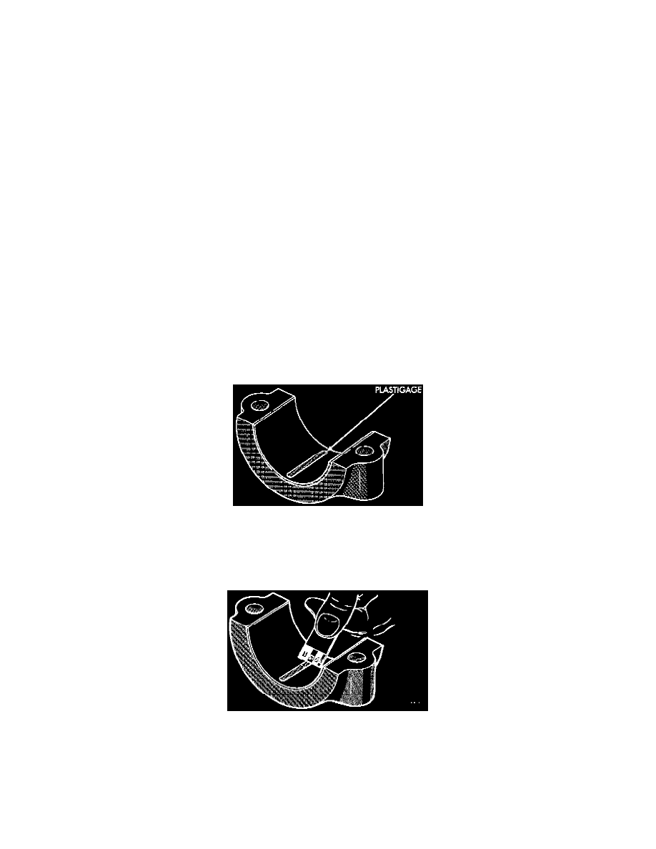
1. Place a piece of Plastigage across the entire width of the bearing cap shell. Position the Plastigage approximately 6.35 mm (1/4 inch) off center
and away from the oil holes. In addition, suspect areas can be checked by placing the Plastigage in that area. Tighten the bearing cap bolts of the
bearing being checked to required torque. DO NOT rotate the crankshaft or the Plastigage may be smeared, giving inaccurate results.
Fig.2 Placement Of Plastigage In Bearing Shell
2. Remove the bearing cap and compare the width of the flattened Plastigage with the scale provided on the package. Plastigage generally comes in 2
scales (one scale is in inches and the other is a metric scale). Locate the band closest to the same width. This band shows the amount of clearance.
Differences in readings between the ends indicate the amount of taper present. Record all readings taken.
Fig.3 Clearance Measurement
3. Plastigage is available in a variety of clearance ranges. The 0.025 - 0.076 mm (0.001 - 0.003 inch)range is usually the most appropriate for
checking engine bearing clearances.
CONNECTING ROD BEARING CLEARANCE
Engine connecting rod bearing clearances can be determined by use of Plastigage, or equivalent. The following is the recommended procedures for the
use of Plastigage: