
Cherokee 4WD L6-4.0L VIN S (1998)
Horn Relay: Testing and Inspection
WARNING: ON VEHICLES EQUIPPED WITH AIRBAGS, REFER TO AIR BAGS AND SEAT BELTS/AIR BAGS BEFORE
ATTEMPTING ANY STEERING WHEEL, STEERING COLUMN, OR INSTRUMENT PANEL COMPONENT DIAGNOSIS OR SERVICE.
FAILURE TO TAKE THE PROPER PRECAUTIONS COULD RESULT IN ACCIDENTAL AIRBAG DEPLOYMENT AND POSSIBLE
PERSONAL INJURY.
Horn Relay
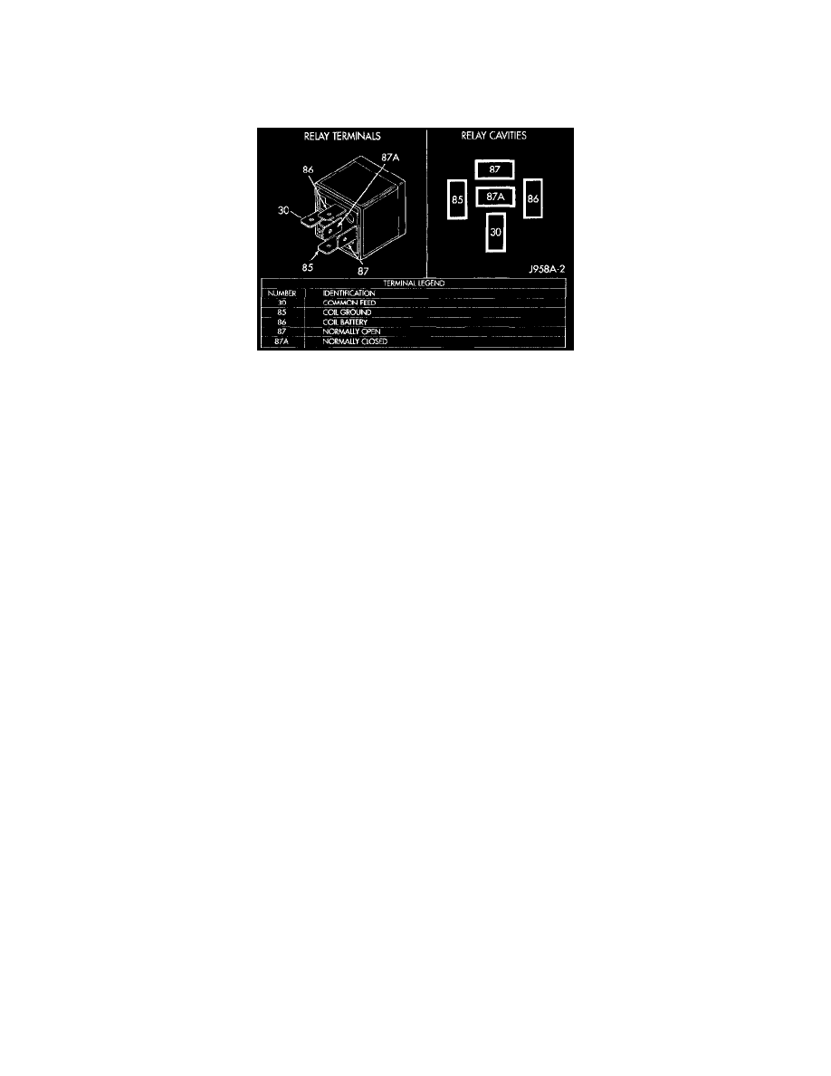
Relay Test
The horn relay is located in the junction block. The junction block is attached to the right cowl side inner panel, below the instrument panel and
behind the right cowl side trim panel.
Remove the horn relay from the junction block as described to perform the following tests:
1. A relay in the de-energized position should have continuity between terminals 87A and 30, and no continuity between terminals 87 and 30. If OK,
go to Step 2. If not OK, replace the faulty relay
2. Resistance between terminals 85 and 86 (electromagnet) should be 75 ± 5 Ohms. If OK, go to Step 3. If not OK, replace the faulty relay.
3. Connect a battery to terminals 85 and 86. There should now be continuity between terminals 30 and 87, and no continuity between terminals 87A
and 30. If OK, see the Relay Circuit Test. If not OK, replace the faulty relay.
Relay Circuit Test
1. The relay common feed terminal cavity (30) is connected to battery voltage and should be hot at all times. If OK, go to Step 2. If not OK, repair
the open circuit to the fuse in the junction block as required.
2. The relay normally closed terminal (87A) is connected to terminal 30 in the de-energized position, but is not used for this application. Go to Step
3.
3. The relay normally open terminal (87) is connected to the common feed terminal (30) in the energized position. This terminal supplies battery
voltage to the horn(s). There should be continuity between the cavity for relay terminal 87 and the relay output circuit cavity of each horn wire
harness connector at all times. If OK, go to Step 4. If not OK, repair the open circuit to the horn(s) as required.
4. The coil battery terminal (86) is connected to the electromagnet in the relay It is connected to battery voltage and should be hot at all times. Check
for battery voltage at the cavity for relay terminal 86. If OK, go to Step 5. If not OK, repair the open circuit to the fuse in the junction block as
required.
5. The coil ground terminal (85) is connected to the electromagnet in the relay It is grounded through the horn switch when the horn switch is
depressed. Check for continuity to ground at the cavity for relay terminal 85. There should be continuity with the horn switch depressed, and no
continuity with the horn switch released. If not OK, see the diagnosis for the Lighting and Horns/Horns/Horn Switch.