
Cherokee 4WD V6-173 2.8L VIN W 2-bbl (1985)
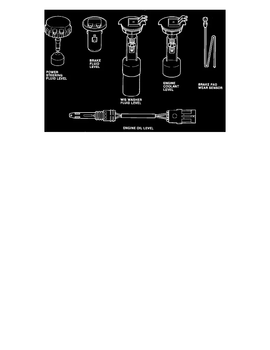
Fig. 2 - Fluid Level and Wear Sensors
^
Fluid level/wear sensors mounted in the various components being monitored (Fig. 2).
^
The necessary interconnecting wires.
Module, Sensors, Fluid Levels, Brake Pad Wear
DISPLAY MODULE WARNING LIGHTS
The system warning lights are contained in the display module mounted in the instrument cluster. Three different color warning lights are used in the
module.
Amber checking lights indicate that each of the various systems is being checked.
A green light indicates that the fluid level or pads are OK.
A red light indicates that the fluid level or pads should be checked and corrected if necessary.
NOTE:
Disconnected fluid level sensor wires or open circuits will also cause a red light to illuminate. (However, no red light illuminates for
disconnected brake pad wear sensor wires.)
REMOTE MODULE
The preprogrammed remote electronic module analyzes electrical current flow through the sensors connected to it. The current varies according to the
fluid level. An OK level generates a different current flow than does a low level.
The remote module analyzes the current flow received during the checking process and triggers the appropriate warning light on the display module. The
engine, transmission, transfer case, front axle and rear axle oil level sensors are connected to the remote module.
SENSORS
The sensors are mounted directly in the component being monitored.
Sensor locations are as follows:
^
Engine coolant - in the coolant recovery bottle.
^
Engine oil - in the oil pan.
^
Power steering fluid - in the pump reservoir.