
CJ-7 L4-150 2.5L VIN U 1-bbl (1983)
Driver/Vehicle Information Display: Testing and Inspection
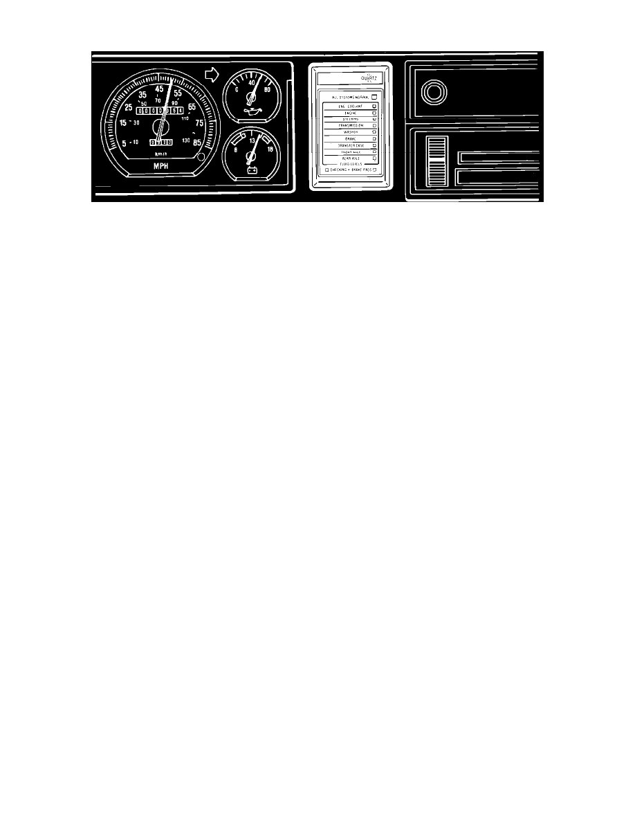
Fig. 4 Systems Sentry System warning light display module
DESCRIPTION & OPERATION
This system, available on some models, is a diagnostic warning system used to monitor vital fluid levels and disc brake pad wear.
The system consists of a warning light display module mounted on right side of instrument cluster, a remote module under the dash, various fluid level
and wear sensors and the necessary interconnecting wiring.
The warning light display module in the instrument cluster contains three different color lights. The amber checking lights indicate that each system is
being checked. The green lights indicate that fluid level or brake pads are satisfactory. The red lights indicate that fluid level or brake pads should be
checked and corrected as necessary. It should be noted that disconnected fluid level sensor wires or open circuits will cause a red warning light, however,
disconnected brake pad wear sensor wires will not create any indication.
The remote module monitors and analyzes electrical current flow through the sensors connected to it. Because current varies with fluid level, the
module is able to energize the appropriate warning light on the display module. The engine, transmission, transfer case and rear axle oil level sensors are
connected to the remote module.
The various sensors and their locations are as follows: engine coolant, located in the coolant recovery bottle; engine oil, located in the oil pan; power
steering fluid, located in the pump reservoir; manual transmission oil, located in the transmission fill plug; automatic transmission fluid, located on the
transmission dipstick; windshield washer fluid, located in the washer reservoir; brake fluid, located in the master cylinder; transfer case oil, located in the
rear section of the transfer case; front and rear axle oil, located in front and rear axle housings; front disc brake pads, located on each inboard brake pad.
The engine, transfer case, transmission and axle oil level sensors operate on the principle of changes in resistance in relation to contact with oil and are
connected to the remote module. The power steering, brake fluid, windshield washer and engine coolant sensors are float-type sensors affected by
changes in fluid level and are wired directly to the display module. The brake pad wear sensor is also wired directly to the display module and is an
electromechanical device actuated by contact with the rotor surface. When the pad is worn enough to allow sensor to contact rotor, the sensor grounds
against the rotor. This creates a brief current surge on the pad warning circuit and shorts the 4 amp in-line signal fuse, resulting in illumination of the red
warning light.
CHECKING FLUID LEVELS AND/OR BRAKE PAD WEAR
1.
Operate vehicle until fluids reach normal operating temperature.
2.
Park vehicle on a level surface.
3.
Turn ignition to Off position and observe display module indicator lights, noting the following:
a. Amber lights indicate that all systems are being checked.
b. A green light indicates that the fluid level or pad wear is satisfactory.
c. A red light indicates that the fluid level or pad wear should be checked.
4.
To repeat warning light display, restart engine and idle for 30 seconds, then turn ignition to Off position.