
Comanche 2WD L4-150 2.5L VIN E TBI (1989)
Crankshaft Position Sensor: Description and Operation
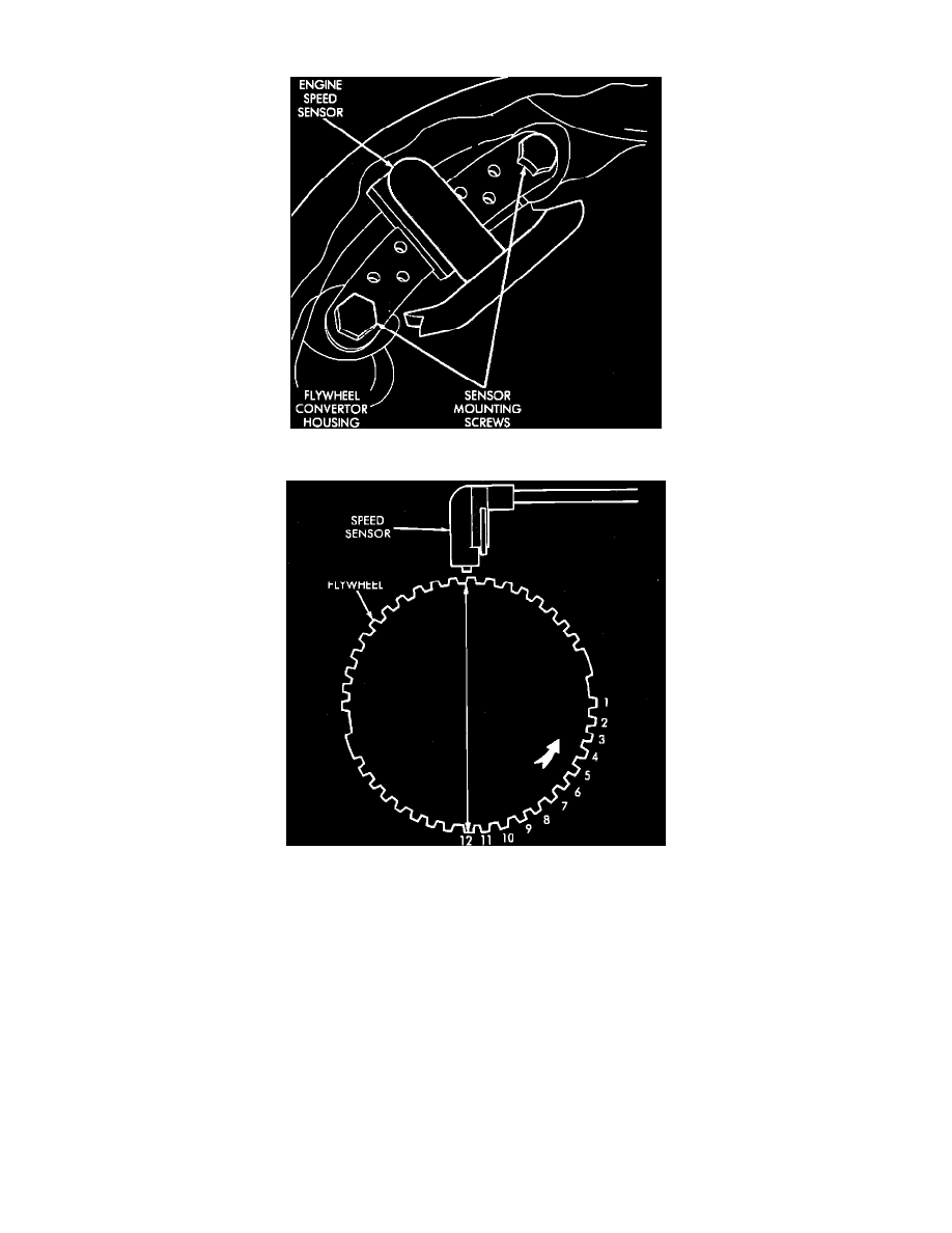
Engine Speed Sensor
Engine Speed Sensor and Flywheel
This sensor is located on the bellhousing of the transmission, and is used to send voltage signals, relating to engine speed and piston position, to the
ECU. The ECU converts the signals, rate of change of crankshaft angle and crankshaft angle, into engine RPM and piston position respectively. It has a
magnetic core inside it that creates a voltage output when a conductor passes through the magnetic flux that it emits. The flywheel has a large drive plate
with four large trigger teeth (each 90 degrees before top dead center of its respective cylinder), and twelve small teeth in between the trigger teeth and
top dead center of each cylinder.
When a small tooth and notch passes under the magnetic core in the sensor, they move through the lines of magnetic flux emitted by the sensor. As these
teeth approach the lines of magnetic flux, they cause the magnetic field to concentrate or intensify, and as the teeth pass through the magnetic field, the
magnetic field collapses. This concentration and collapsing of the magnetic field causes voltage spikes in the sensors pick-up winding. The ECU sees
every one of these voltage spikes and counts them as they pass the sensor.
When a large tooth and notch passes under the sensor, a larger voltage spike is induced. This large spike indicates to the ECU that TDC of that cylinder
will be occurring 12 teeth later. Through the use of the Engine Speed Sensor (CPS) and other sensor inputs the ECU controls (advances or retards) the
ignition timing.