
Comanche 2WD L6-242 4.0L VIN S MFI (1992)
30.
To relieve spring tension on tilt-release lever pin and lock shoe pin, insert wedge between lock shoes and lock cylinder housing.
31.
Using pin punch, remove tilt-release lever pin from lock cylinder housing.
32.
Using pin punch, remove lock shoe pin from lock cylinder housing.
33.
Remove lock shoes, springs and wedge.
34.
Check upper and lower bearings and races for damage or wear. If necessary, remove from lock cylinder and discard.
35.
Remove steering shaft from upper end of steering column.
36.
Separate steering shaft by folding it 90° at flexible joint and detaching upper lower shaft halves.
37.
Remove column support attaching bolts, then the column support.
38.
Remove shift gate attaching screws, then shift gate from column support.
39.
Remove retainer and bearing from lower end of steering column.
40.
Remove shift tube retaining ring and thrust washer.
41.
Using suitable puller, remove shift tube from steering column jacket.
42.
Tilt upper end of retainer plate toward lower end of column, turn plate counterclockwise and remove plate.
43.
On column shift models, remove wave washer and shift tube spring.
44.
On column shift models, remove shift bowl from steering column jacket.
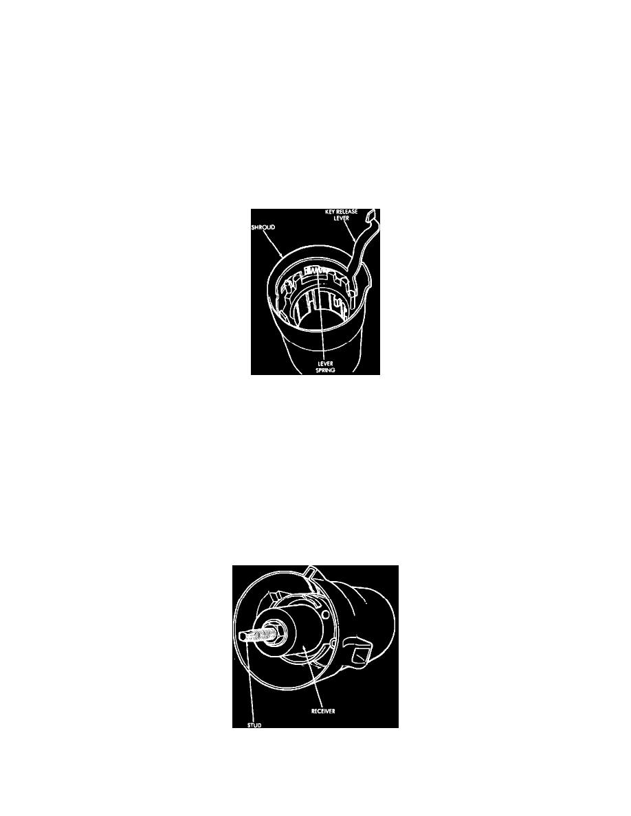
Fig. 49 Key release lever & spring removal
45.
On console shift models, remove key-release lever and lever spring from shroud. To remove lever, tilt lever forward and lift upward.
Column Shift Models
Use only original or exact replacement screws, bolts and nuts to assemble steering column. Failure to use original or exact replacement parts
could prevent column from compressing upon impact.
Apply chassis lubricant to all bearing, thrust and friction producing mating surfaces before assembly.
1.
Install shift bowl on steering column jacket.
2.
Install shift tube spring, wave washer and retainer plate in shift bowl.
3.
Insert shift tube through lower end of steering column aligning tube key/spline with shift bowl keyway.
4.
Insert installation tools in shift tube. The spring loaded lower foot of tool must engage shift tube inner shoulder and tool guide must be
seated in shift tube. Tighten nut on stud only enough to obtain a snug fit against spring tension.
Fig. 50 Shift tube installation
5.
Remove nut and place receiver installation tool over stud.
6. Install and tighten nut to force shift tube into shift bowl. Remove installation tools.