
Comanche 2WD L6-242 4.0L VIN S MFI (1992)
7.
Install shift tube thrust washer and retainer plate snap ring.
8.
Install lower bearing in steering column.
9.
Position shift gate in steering column support, then install attaching screws.
10.
Position steering column support in steering column.
11.
Install steering column support attaching screws finger-tight, then torque alternately and evenly to 60 inch lbs.
12.
Install remote rod in steering column support. Route rod through upper end of shroud and insert it into rod slot located in support.
13.
Install dimmer and ignition switches.
14.
Install steering shaft in steering column.
15.
If removed, lubricate and install new races and bearings in lock cylinder.
16.
Using an 0.18 inch diameter rod for alignment, install lock shoes, lock shoe springs and lock shoe pins in lock cylinder housing.
17.
Install tilt-release lever, lever spring and lever pin into lock cylinder housing. Insert wedge between housing and lever to relieve spring
tension.
18.
Install lock bolt in lock cylinder housing engaging bolt in lock sector cam surface.
19.
Install lock rack, rack preload spring and new shim in lock cylinder housing. Square block tooth on lock rack must mate with square block tooth
on lock sector.
20.
Install lock spring and spring retaining screw. Torque screw to 35 inch lbs.
21.
Align and install assembled lock cylinder housing on steering column support. Retain lock shoes in disengaged position.
22.
Align pivot pin holes in lock cylinder housing with those in steering column support and install pivot pins. Use punch and hammer to seat pins
completely.
23.
Insert tilt-release lever in lock cylinder housing, then place housing in full-upward tilt position.
24.
Lubricate tilt spring guide and tilt spring, then position spring on guide.
25.
Insert tilt spring guide and spring into lock cylinder housing, then install guide retainer over spring. Ensure retainer lock tabs are engaged with
housing lugs.
26.
Place cover on lock cylinder housing. Install retaining screws, torquing screws to 60 inch lbs.
27.
Install gear selector indicator cover and retaining screws.
28.
Route dimmer switch wire harness and gear selector indicator wires through steering column.
29.
Install lock cylinder housing. Rotate cylinder until cylinder key is aligned with keyway in housing. Install retaining screw and torque to 40 inch
lbs.
30.
Insert ignition key in cylinder and turn to On position, then install key warning buzzer switch.
31.
Install turn signal switch. Do not install retaining screws at this time.
32.
Install windshield wiper wire harness and switch. Route wire harness down through column jacket.
33.
If equipped, route cruise control wire harness through steering column jacket.
34.
Install turn signal/wiper/dimmer switch/cruise control (if equipped) stalk.
35.
Insert hazard warning knob in switch and press inward. Install turn signal switch retaining screws. Ensure switch is properly seated before
tightening screws. Torque attaching screws to 33 inch lbs. Thread hazard warning switch knob into switch and pull knob outward.
36.
Install and seat upper bearing race in lock cylinder housing.
37.
Install upper bearing preload spring, canceling cam and lockplate.
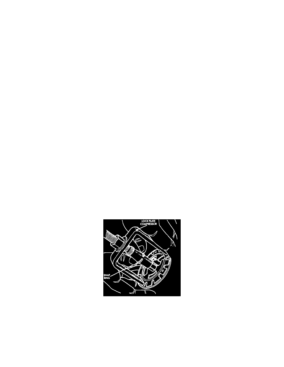
Fig. 45 Installing lockplate snap ring
38.
Install new lockplate retaining snap ring on sleeve of compressor tool, then tool on steering shaft.
39.
Compress lockplate with compressor tool and position snap ring in steering shaft groove.
40.
Remove compressor tool. Ensure snap ring is completely seated in groove before removing tool.
41.
Install lockplate cover, then gear selector lever and retaining pin.
42.
Install steering wheel.
43.
Insert ignition key in lock cylinder. Turn cylinder to Off position, then move ignition switch downward to eliminate any switch-to-rod lash.
Torque switch attaching screws to 35 inch lbs.
44.
Depress dimmer switch slightly and insert a 3/32 inch drill bit into adjustment hole.