
Comanche 4WD L6-242 4.0L VIN L FI (1990)
Oxygen Sensor Heater Relay: Testing and Inspection
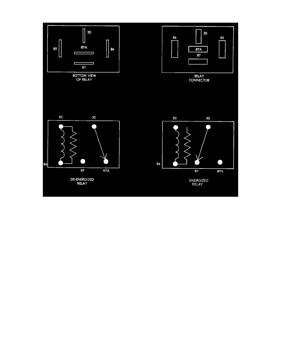
Relay Terminal Identification
OXYGEN SENSOR HEATER RELAY TERMINAL IDENTIFICATION
The following is a list of the terminal numbers, with circuit codes, and color codes, and their function:
Circuit No. Terminal No.
Color Code
Description
F22
4
OR/BK
This circuit provides a switched voltage source to the fuel pump (bypassing the ballast resistor).
F86
2
GY/YL
This circuit is the voltage source for the oxygen sensor heater relay, from the ECU.
F22
1
OR
This circuit provides voltage to the fuel pump via the ballast resistor.
63
3
OR
This circuit provides battery input voltage to the oxygen sensor heating element.
11
5
YL
This circuit provides the ground path for the oxygen sensor heater relay to the ECU.
OXYGEN SENSOR HEATER RELAY TEST
NOTE: The oxygen sensor heater relay operation may be tested with the use of the DRB II scanner or equivalent. See: Testing and Inspection/Scan
Tool Testing and Procedures
If no scanner is available proceed with the following test.
NOTE: The fuel system wiring diagrams should be used in conjunction with the following test to correctly diagnose the problem.
1.
Pull the oxygen sensor heater relay out of its connector and connect a voltmeter to the Orange F22 wire (terminal 1). With the engine running, or
for 2 to 3 seconds while starting, battery voltage should be present at this terminal. If no voltage is present, refer to FUEL PUMP RELAY TEST