
Commander 2WD V6-3.7L VIN K (2006)
not place the target wheel near a magnetic source of any kind. A damaged or magnetized target wheel could cause a vehicle no start condition.
CAUTION: Do not forcefully rotate the camshafts or crankshaft independently of each other. Damaging intake valve to piston contact will occur.
Ensure negative battery cable is disconnected to guard against accidental starter engagement.
14. Remove left and right camshaft sprocket bolts.
15. While holding the left camshaft steel tube with Special Tool 8428 Camshaft Wrench (2), remove the left camshaft sprocket. Slowly rotate the
camshaft approximately 5 degrees clockwise to a neutral position.
16. While holding the right camshaft steel tube with Special Tool 8428 Camshaft Wrench (2), remove the right camshaft sprocket.
17. Remove idler sprocket assembly bolt.
18. Slide the idler sprocket assembly and crank sprocket forward simultaneously to remove the primary and secondary chains.
19. Remove both pivoting tensioner arms and chain guides.
20. Remove primary chain tensioner.
INSPECTION
Inspect the following components: Sprockets for excessive tooth wear. Some tooth markings are normal and not a cause for sprocket replacement.
Idler sprocket assembly bushing and shaft for excessive wear. Idler sprocket assembly spline joint. The joint should be tight with no backlash or axial
movement. Chain guides and tensioner arms. Replace these parts if grooving in plastic face is more than 1 mm (0.039 inch) deep. If plastic face is
severely grooved or melted, the tensioner lube jet may be clogged. The tensioner should be replaced.
^
Secondary chain tensioner piston and ratcheting device. Inspect for evidence of heavy contact between tensioner piston and tensioner arm. If this
condition exist the tensioner arm and chain should be replaced.
^
Primary chain tensioner plastic faces. Replace as required.
INSTALLATION
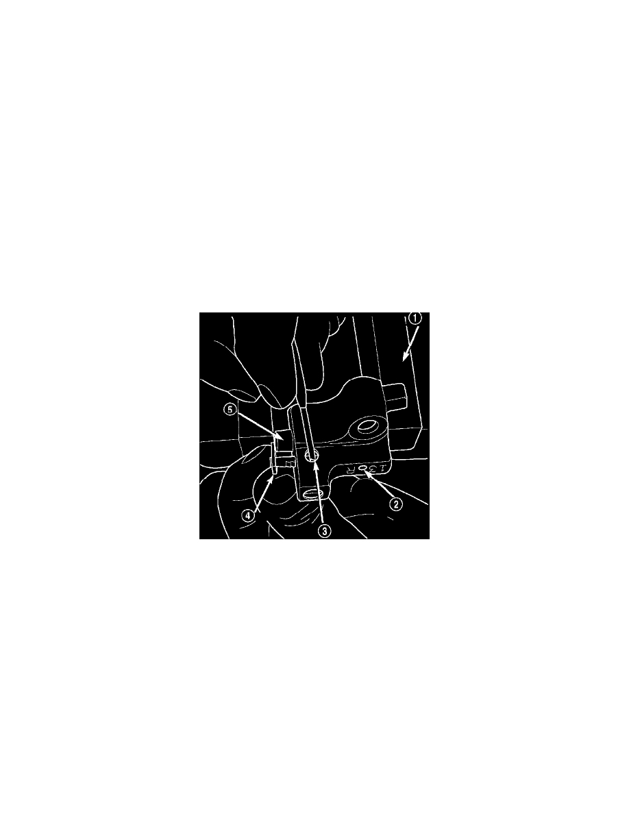
1. Using a vise, lightly compress the secondary chain tensioner piston until the piston step (5) is flush with the tensioner body. Using a pin or suitable
tool, release ratchet pawl (4) by pulling pawl back against spring force through access hole on side of tensioner. While continuing to hold pawl
back, Push ratchet device to approximately 2 mm from the tensioner body. Install Special Tool 8514 lock pin (2) into hole on front of tensioner.
Slowly open vise to transfer piston spring force to lock pin.
2. Position primary chain tensioner over oil pump and insert bolts into lower two holes on tensioner bracket. Tighten bolts to 28 Nm (250 inch lbs.).
3. Install right side chain tensioner arm. Install Torx(R) bolt. Tighten Torx(R) bolt to 28 Nm (250 inch lbs.).
CAUTION: The silver bolts retain the guides to the cylinder heads and the black bolts retain the guides to the engine block.
4. Install the left side chain guide. Tighten the bolts to 28 Nm (250 inch lbs.).
5. Install left side chain tensioner arm, and Torx(R) bolt. Tighten Torx(R) bolt to 28 Nm (250 inch lbs.).
6. Install the right side chain guide. Tighten the bolts to 28 Nm (250 inch lbs.).