
Commander 2WD V8-4.7L Flex Fuel (2009)
the information to confirm safety requirements are met. The control module will then signal the liftgate mounted latch assembly to release the liftgate
from its primary closed and latched position to the ajar and movable position. Once the liftgate control module detects "liftgate ajar", the control module
will provide 12v power to the liftgate motor. The motor will then rotate the drive unit moving the liftgate into the full open position.
LIFTGATE IS OPEN
The power liftgate close command can be initiated by either one press of the power liftgate overhead console switch or two presses of the key fob power
liftgate button. The overhead console switch is hardwired to the power liftgate control module, where as the key fob signal is sent out on the Controller
Area Network (CAN) Data Bus circuit. This signal is detected by the power liftgate control module. The power liftgate control module then interprets
the information to confirm safety requirements are met. The control module will then provide 12v power to the liftgate motor. The motor will then rotate
the drive unit moving the liftgate into the closed position. Once the liftgate mounted latch reaches the body mounted striker assembly, the power latch
takes over to cinch the liftgate to the fully closed and latched position.
If an obstacle is encountered during a power open or close cycle, the power liftgate control module will automatically reverse direction of the liftgate to
prevent vehicle damage or personal injury.
Power Liftgate Link Rod - Description
DESCRIPTION
WARNING: Never attempt to operate the power liftgate system when the link rod is removed or disconnected. Damage to the power liftgate
system will result.
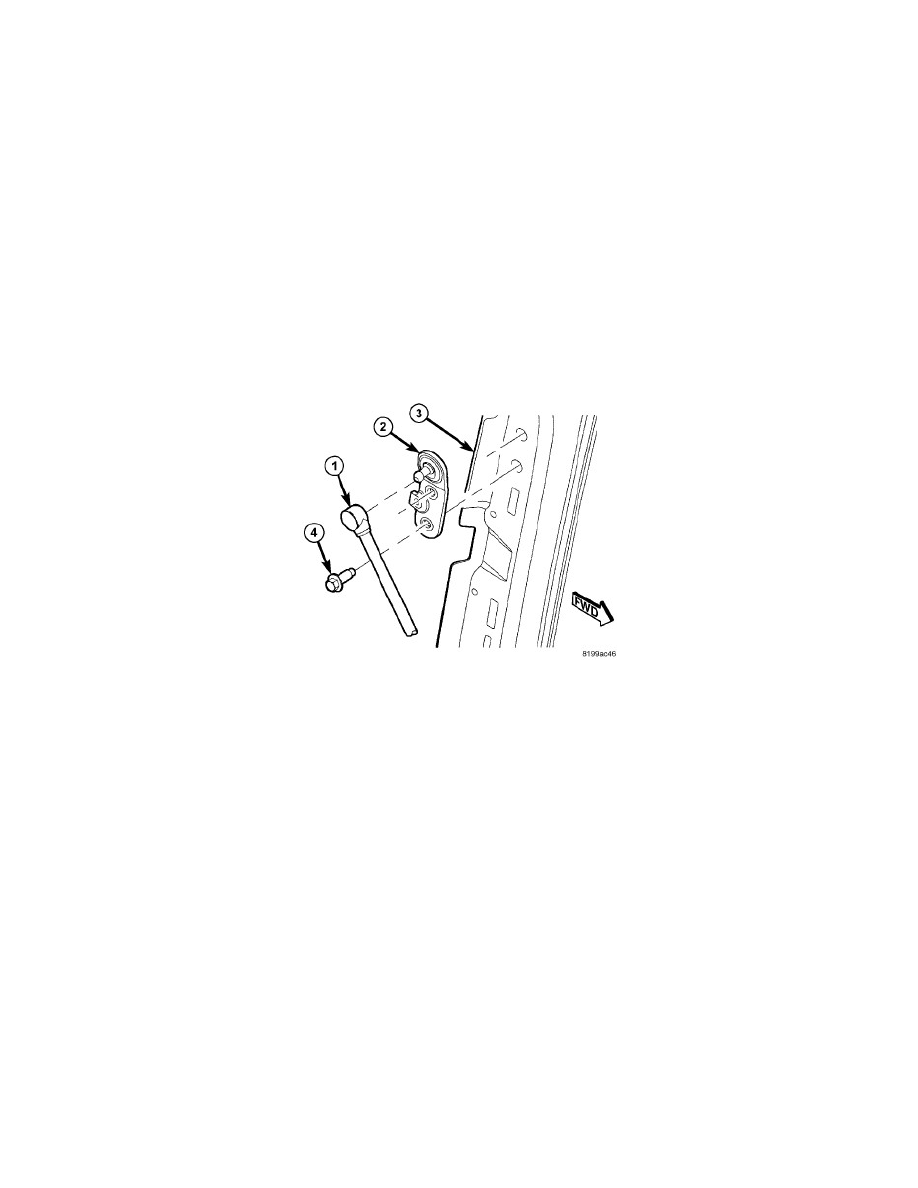
Vehicles equipped with a power liftgate utilize a link rod (1) assembly. This link rod is located in the left rear of the vehicle and is visible without
removing the D-pillar trim. The link rod attaches to the liftgate pivot bracket (2) at one end and the power liftgate drive unit assembly at the other. The
link rod consists of a steel shaft, equipped with two spherical rod end receptacles at each end. The weight of the liftgate is not supported by the link rod,
the liftgate prop rods are designed to support the liftgate.
The link rod cannot be adjusted or repaired and if inoperative, must be replaced. See: Service and Repair/Power Liftgate Link Rod - Removal.
Power Liftgate Link Rod - Operation
OPERATION
One end of the link rod assembly is attached to the liftgate pivot bracket, the other end is attached to the power liftgate drive unit. When the drive unit is
driven by the liftgate motor assembly the liftgate is moved to the open or closed position.