
Commander 4WD V8-4.7L VIN N (2006)
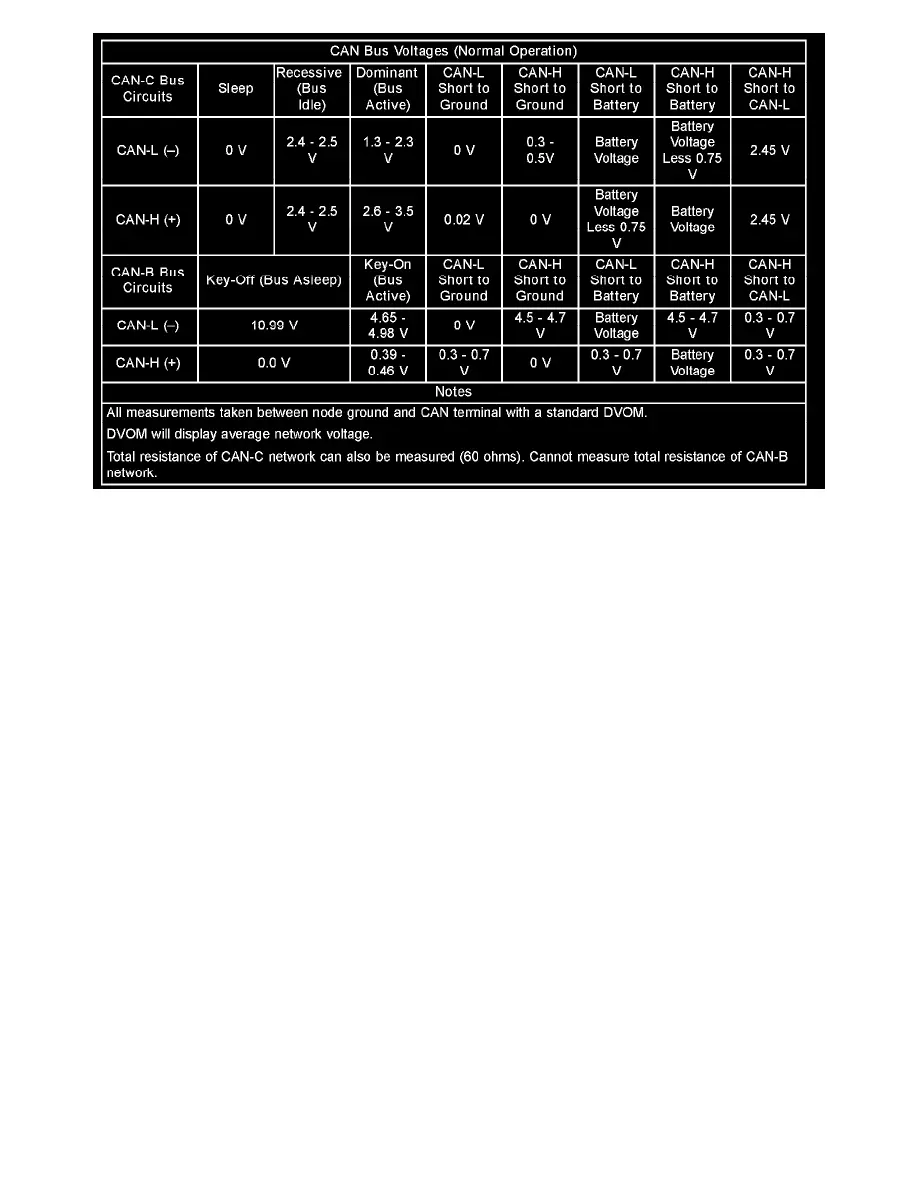
CAN Bus Voltages (Normal Operation)
The CAN bus nodes are connected in parallel to the two-wire bus using a twisted pair, where the wires are wrapped around each other to provide
shielding from unwanted electromagnetic induction, thus preventing interference with the relatively low voltage signals being carried through them. The
twisted pairs have between 33 and 50 twists per meter. While the CAN bus is operating (active), one of the bus wires will carry a higher voltage and is
referred to as the CAN High or CAN bus (+) wire, while the other bus wire will carry a lower voltage and is referred to as the CAN Low or CAN bus (-)
wire. Refer to the CAN Bus Voltages table.
In order to minimize the potential effects of Ignition-Off Draw (IOD), the CAN-B network employs a sleep strategy. However, a network sleep strategy
should not be confused with the sleep strategy of the individual nodes on that network, as they may differ. For example: The CAN-C bus network is
awake only when the ignition switch is in the ON or START positions; however, the FCM, which is on the CAN-C bus, may still be awake with the
ignition switch in the ACCESSORY or UNLOCK positions. The integrated circuitry of an individual node may be capable of processing certain sensor
inputs and outputs without the need to utilize network resources.
The CAN-B bus network remains active until all nodes on that network are ready for sleep. This is determined by the network using tokens in a manner
similar to polling. When the last node that is active on the network is ready for sleep, and it has already received a token indicating that all other nodes
on the bus are ready for sleep, it broadcasts a bus sleep acknowledgment message that causes the network to sleep. Once the CAN-B bus network is
asleep, any node on the bus can awaken it by transmitting a message on the network. The FCM will keep either the CAN-B or the CAN-C bus awake for
a timed interval after it receives a diagnostic message for that bus over the Diagnostic CAN-C bus.
In the CAN system, available options are configured into the FCM at the assembly plant, but additional options can be added in the field using the
diagnostic scan tool. The configuration settings are stored in non-volatile memory. The FCM also has two 64-bit registers, which track each of the
as-built and currently responding nodes on the CAN-B and CAN-C buses. The FCM stores a Diagnostic Trouble Code (DTC) in one of two caches for
any detected active or stored faults in the order in which they occur. One cache stores powertrain (P-Code), chassis (C-Code) and body (B-Code) DTCs,
while the second cache is dedicated to storing network (U-Code) DTCs.
If there are intermittent or active faults in the CAN network, a diagnostic scan tool connected to the Diagnostic CAN-C bus through the 16-way Data
Link Connector (DLC) may only be able to communicate with the FCM. To aid in CAN network diagnosis, the FCM will provide CAN-B and CAN-C
network status information to the scan tool using certain diagnostic signals. In addition, the transceiver in each node on the CAN-C bus will identify a
bus off hardware failure, while the transceiver in each node on the CAN-B bus will identify a general bus hardware failure. The transceivers for some
CAN-B nodes will also identify certain failures for both CAN-B bus signal wires.