
Commander 4WD V8-4.7L VIN N (2006)
Connector views show the connector and the circuits involved with that connector. The connectors are identified using the name/number on the diagram
sheets, and a master list can be found at Vehicle/Diagrams.
Connector, Ground and Splice Identification and Location
CAUTION: Not all connectors are serviced. Some connectors are serviced only with a harness. A typical example might be the Supplemental Restraint
System connectors. Always check parts availability before attempting a repair.
Identification
Connectors, grounds, and splices are identified as follows:
-
In-line connectors located in the engine compartment are C100 series numbers
-
In-line connectors located in the Instrument Panel area are C200 series numbers.
-
In-line connectors located in the body are C300 series numbers.
-
Jumper harness connectors are C400 series numbers.
-
Grounds and ground connectors are identified with a "G" and follow the same series numbering as the in-line connectors.
-
Splices are identified with an "S" and follow the same series numbering as the in-line connectors.
-
Component connectors are identified by the component name instead of a number. Multiple connectors on a component use a C1, C2, etc.
identifier.
Locations
Vehicle/Locations contains the master connector/ground/splice location index charts with hyperlinks to the applicable location illustrations. The
illustrations contain the connector name (or number)/ground number/splice number and component identification.
The abbreviation T/O is used in the location column to indicate a point in which the wiring harness branches out to a component. The abbreviation
N/S means Not Shown in the illustrations.
PLEASE NOTE: The master location index charts contain numerous items that may not be applicable to all vehicle models. If a link on the master
location index chart to a figure is not functional, that means that the chart item and/or figure in question does NOT apply to the vehicle model selected.
Connector Replacement
REMOVAL
1. Disconnect battery
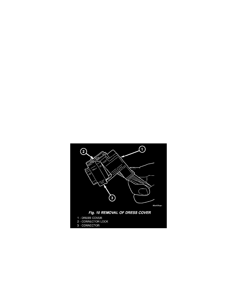
Fig.10 Removal Of Dress Cover
2. Release Connector Lock (Fig. 10).
3. Disconnect the connector being repaired from its mating half/component.
4. Remove the dress cover (if applicable) (Fig. 10).