
Commander 4WD V8-4.7L VIN N (2006)
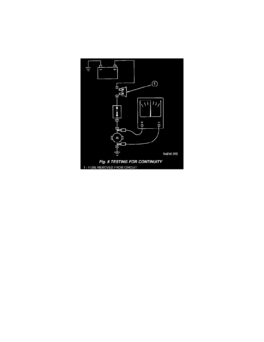
Fig.7 Testing For Voltage Potential
STANDARD PROCEDURE - TESTING OF VOLTAGE POTENTIAL
1. Connect the ground lead of a voltmeter to a known good ground (Fig. 7).
2. Connect the other lead of the voltmeter to the selected test point. The vehicle ignition may need to be turned ON to check voltage. Refer to the
appropriate test procedure.
STANDARD PROCEDURE - TESTING FOR CONTINUITY
1. Remove the fuse for the circuit being checked or, disconnect the battery.
Fig.8 Testing For Continuity
2. Connect one lead of the ohmmeter to one side of the circuit being tested (Fig. 8).
3. Connect the other lead to the other end of the circuit being tested. Low or no resistance means good continuity.
STANDARD PROCEDURE - TESTING FOR A SHORT TO GROUND
1. Remove the fuse and disconnect all items involved with the fuse.
2. Connect a test light or a voltmeter across the terminals of the fuse.
3. Starting at the fuse block, wiggle the wiring harness about six to eight inches apart and watch the voltmeter/test lamp.
4. If the voltmeter registers voltage or the test lamp glows, there is a short to ground in that general area of the wiring harness.
STANDARD PROCEDURE - TESTING FOR A SHORT TO GROUND ON FUSES POWERING SEVERAL LOADS
1. Refer to the wiring diagrams and disconnect or isolate all items on the suspected fused circuits.
2. Replace the blown fuse.
3. Supply power to the fuse by turning ON the ignition switch or re-connecting the battery.
4. Start connecting or energizing the items in the fuse circuit one at a time. When the fuse blows the circuit with the short to ground has been isolated.