
Commander 4WD V8-4.7L VIN N (2006)
Wiper Relay: Description and Operation
Relay-Wiper-Rear
RELAY-WIPER-REAR
DESCRIPTION
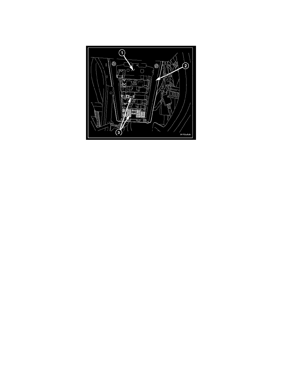
The rear wiper relay is an International Standards Organization (ISO) relay. Relays conforming to the ISO specifications have common physical
dimensions, current capacities, terminal patterns, and terminal functions. This relay is permanently soldered onto the electronic circuit board of the
Junction Block (JB) (1) located underneath the driver side end of the instrument panel. The relay is connected to all of the required inputs and outputs
through five terminals.
The rear wiper relay cannot be adjusted or repaired and, if ineffective or damaged, the entire JB unit must be replaced.
OPERATION
The rear wiper relay is an electromechanical switch that uses a low current input from the Front Control Module (FCM) to control a high current output
to the rear wiper motor. The movable common feed contact point is held against the fixed normally closed contact point by spring pressure. When the
relay coil is energized, an electromagnetic field is produced by the coil windings. This electromagnetic field draws the movable relay contact point away
from the fixed normally closed contact point, and holds it against the fixed normally open contact point. When the relay coil is de-energized, spring
pressure returns the movable contact point back against the fixed normally closed contact point. A resistor is connected in parallel with the relay coil in
the relay, and helps to dissipate voltage spikes and electromagnetic interference that can be generated as the electromagnetic field of the relay coil
collapses.
The rear wiper relay terminals are connected to the vehicle electrical system through soldered connections to the electronic circuit board of the Junction
Block (JB). The inputs and outputs of the rear wiper relay include:
-
Common Feed Terminal - The common feed terminal (30) is connected to battery current from a fuse in the PDC through a fused B(+) circuit at
all times.
-
Coil Ground Terminal - The coil ground terminal (85) is connected to a control output of the FCM through a rear wiper relay control circuit. The
FCM controls rear wiper motor operation by controlling a ground path through this circuit.
-
Coil Battery Terminal - The coil battery terminal (86) is connected to battery current from a fuse in the PDC through a fused B(+) circuit at all
times.
-
Normally Open Terminal - The normally open terminal (87) is connected to the rear wiper motor through the rear wiper relay output circuit.
When the rear wiper relay is energized, the normally open terminal of the relay is connected to battery current from a fuse in the Power
Distribution Center (PDC) through a fused B(+) circuit.
-
Normally Closed Terminal - The normally closed terminal (87A) is not connected to any circuit in this application, but provides a battery current
output only when the rear wiper relay coil is de-energized.
The rear wiper relay can be diagnosed using conventional diagnostic tools and methods. However, conventional diagnostic methods may not prove
conclusive in the diagnosis of the Steering Control Module (SCM), the FCM or the electronic message inputs to or outputs from the SCM and the FCM
that control the operation of the rear wiper relay. The most reliable, efficient, and accurate means to diagnose the rear wiper relay, the SCM, the FCM or
the electronic message inputs and outputs related to the rear wiper relay operation requires the use of a diagnostic scan tool.