
Commander 4WD V8-4.7L VIN N (2006)
Hazard Warning Switch: Description and Operation
HAZARD SWITCH
DESCRIPTION
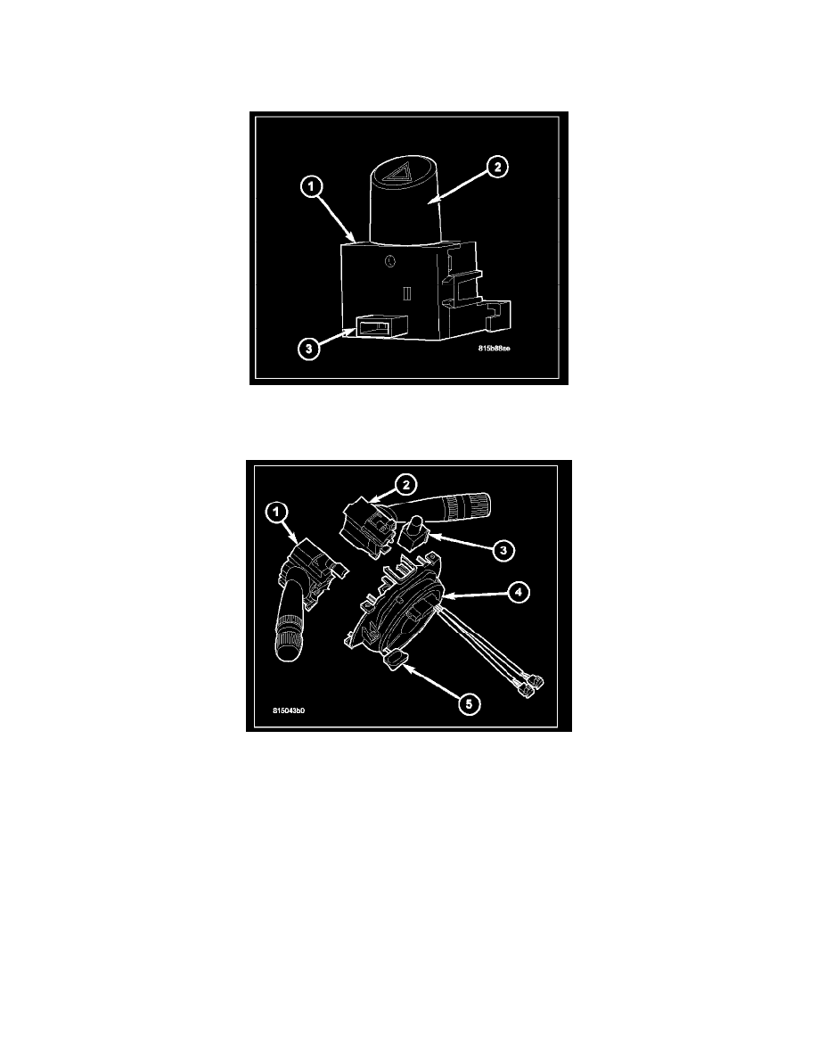
The hazard switch (1) is located on the top of the steering column, just below the steering wheel. This switch is the control for the hazard warning
lighting. The only visible component of the switch is the control push button (2) that extends through the upper steering column shroud on the top of the
column. The remainder of the switch including its mounting provisions and its electrical connection (3) is concealed beneath the shroud.
The switch housing (3) and push button are constructed of molded black plastic. A red, stencil-like International Control and Display Symbol icon for
Hazard Warning identifies the hazard switch button. The switch is secured to the back of the Steering Control Module (SCM) (4) by plastic latch
features integral to the SCM housing. A single integral interface connector with two terminal pins is integral to the switch housing and connects the
switch directly to the SCM.
The hazard switch cannot be adjusted or repaired. If the switch is faulty or damaged, the entire switch unit must be replaced.
OPERATION
The hazard switch features a push-push type latching push button. When the push button is in its latched (lowered) position the switch contacts are open,
and when the push button is in its unlatched (raised) position the switch contacts are closed. Although the hazard switch is mounted to the SCM, the
hazard switch circuits only pass through the SCM. The SCM has no control over and does not monitor the hazard switch output.
The hazard switch receives a ground on one terminal and provides a ground signal output to the Front Control Module (FCM) whenever the switch
contacts are closed. The FCM responds to this input by controlling a battery voltage output and the flash rate for each of the right and left turn signal
lamps, then sends an electronic hazard switch status message over the Controller Area Network (CAN) data bus to the Electromechanical Instrument
Cluster (EMIC) to control the illumination and flash rate of the right and left turn signal indicators, as well as to control the click rate of an
electromechanical relay soldered onto the EMIC electronic circuit board that emulates the sound emitted by a conventional hazard warning flasher.