
Compass 2WD L4-2.4L (2008)
Clockspring Assembly / Spiral Cable: Removal and Replacement
Removal
REMOVAL
WARNING: To avoid serious or fatal injury on vehicles equipped with airbags, disable the Supplemental Restraint System (SRS) before
attempting any steering wheel, steering column, airbag, seat belt tensioner, impact sensor, or instrument panel component diagnosis or service.
Disconnect and isolate the battery negative (ground) cable, then wait two minutes for the system capacitor to discharge before performing
further diagnosis or service. This is the only sure way to disable the SRS. Failure to take the proper precautions could result in accidental
airbag deployment.
NOTE: A service replacement clockspring is shipped with the clockspring pre-centered and with a molded plastic locking pin installed. This
locking pin should not be removed until the steering wheel has been installed on the steering column. If the locking pin is removed before the
steering wheel is installed, the clockspring centering procedure must be performed.
NOTE: When a clockspring is installed into a vehicle without properly centering and locking the entire steering system, the Steering Angle
Sensor (SAS) data does not agree with the true position of the steering system and causes the Electronic Stability Program (ESP) system to shut
down. This may also damage the clockspring without any immediate malfunction. Unlike some other DaimlerChrysler vehicles, this SAS never
requires calibration. See: Procedures.
NOTE: Determining if the clockspring/SAS is centered is also possible electrically using the diagnostic scan tool. Steering wheel position is
displayed as ANGLE with a range of up to 900 degrees. Refer to the appropriate menu item on the diagnostic scan tool.
NOTE: Before starting this procedure, be certain to turn the steering wheel until the front wheels are in the straight-ahead position and that
the entire steering system is locked or inhibited from rotation.
1. Place the front wheels in the straight ahead position and inhibit the steering column shaft from rotation.
2. Disconnect and isolate the battery negative cable.
3. Remove the steering wheel from the steering shaft. See: Steering and Suspension/Steering/Steering Wheel/Service and Repair/Removal.
4. If the removed clockspring is to be reused, be certain to secure the clockspring rotor to the clockspring case to maintain clockspring centering until
the steering wheel is reinstalled on the steering column. If clockspring centering is not maintained, the clockspring must be centered again before
the steering wheel is reinstalled. See: Procedures.
5. Move the steering column to the fully lowered position and leave the tilt release lever in the released (down) position.
6. Remove the upper and lower shrouds from the steering column. See: Steering and Suspension/Steering/Steering Column/Service and
Repair/Removal and Replacement/Steering Column - Removal.
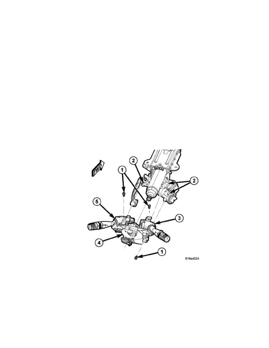
7. Remove the right multi-function switch (3) from the clockspring (4). See: Sensors and Switches/Sensors and Switches - Wiper and Washer
Systems/Wiper Switch/Service and Repair/Removal.
8. Remove the left multi-function switch (5) from the clockspring. See: Lighting and Horns/Sensors and Switches - Lighting and Horns/Combination
Switch/Service and Repair/Removal.
9. Remove the three screws (1) that secure the clockspring to the steering column lock housing (2).