
Grand Cherokee 2WD L6-242 4.0L VIN S MFI (1993)
Camshaft Position Sensor: Description and Operation
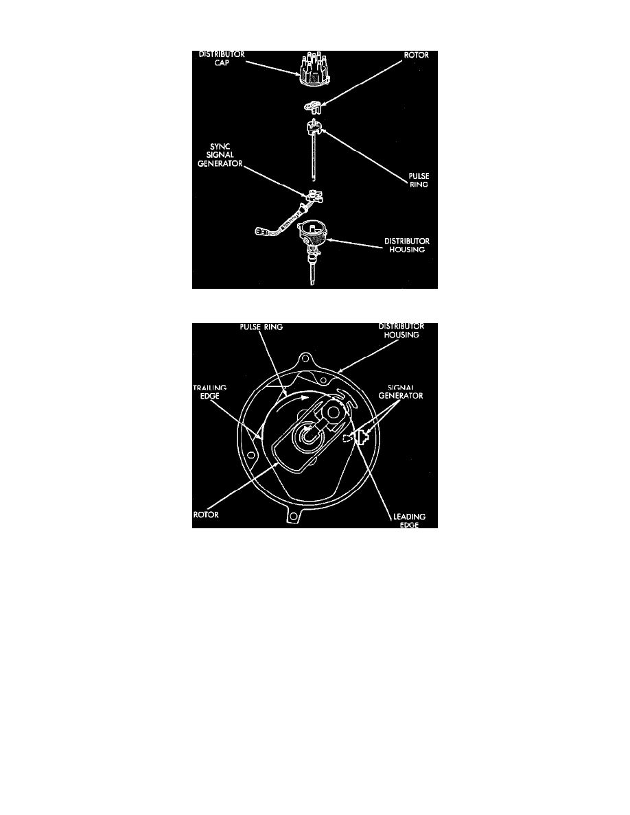
Sync Signal Generator and Pulse Ring
Sync Signal Generator Operation
LOCATION
The camshaft position sensor is located in the distributor housing under the ignition rotor and pulse ring.
PURPOSE
The signal from the camshaft position sensor combined with the input signal from the Crankshaft Position (CKP) Sensor, are what the Powertrain
Control Module (PCM) uses to differentiate between fuel and spark events. Input is also used to properly synchronize fuel injection.
OPERATION
The camshaft position sensor is used to reference number 3 and 4 cylinders, it sends voltage to the PCM and works in conjunction with the CKP so
that the PCM can establish and maintain the correct injector firing order.
The camshaft position sensor consists of a hall effect switch and a pulse ring that is mounted to the distributor shaft. As the leading edge of the
pulse ring passes the hall effect switch, the change in the magnetic field induces a voltage rise of 5 volts. This 5 volt signal indicates to the PCM
that the next piston to come to TDC is number 3. When the trailing edge of the pulse ring leaves the switch, the collapse of the magnetic field
causes the voltage to drop to 0 volts. A signal of 0 volts indicates to the PCM that piston number 4 is the next piston to reach TDC.
If PCM does not sense input from sensor, it will deactivate Automatic Shutdown (ASD) and fuel pump relay, interrupting voltage to fuel pump,
fuel injectors, and ignition coil, causing a no start condition.