
Grand Cherokee 2WD L6-4.0L VIN S (1997)
Transfer Case Switch
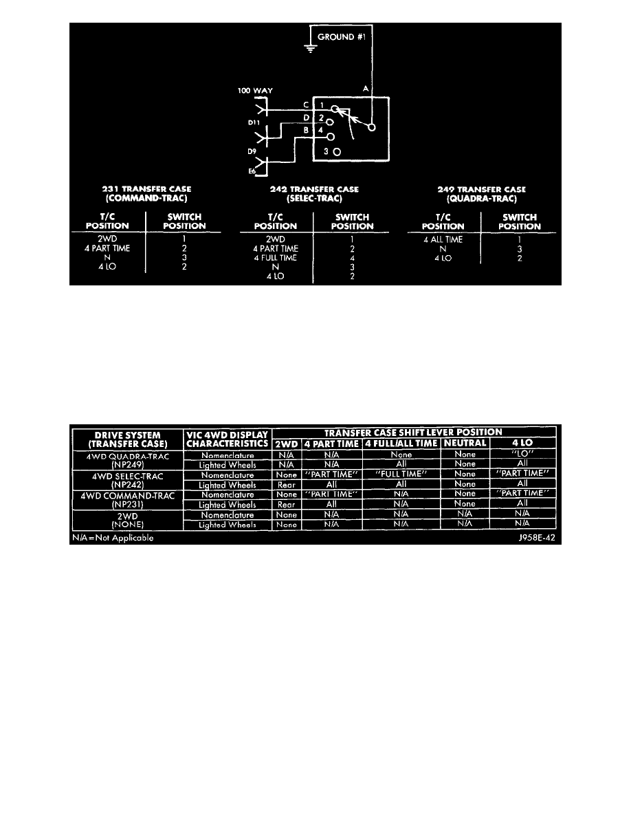
2. Check the transfer case switch continuity while shifting the transfer case shift lever to the proper positions. The switch continuity should be as
shown. If OK, go to Step 3. If not OK, replace the faulty switch.
3. Disconnect and isolate the battery negative cable. Remove the VIC module as described. Unplug the VIC module wire harness connector.
4. Locate two pairs of wire harness connectors located in the wire harness leading to the VIC module. The wire harness connectors should be taped
back to the harness. One pair of connectors are black with a single cavity. The other pair are red with two cavities. If the vehicle has the
Quadra-Trac 4WD transfer case, only the red wire harness connectors should be joined. If the vehicle has the Command-Trac or Selec-Trac 4WD
transfer case, only the black wire harness connectors should be joined. In all cases, only one pair of wire harness connectors should be joined. If
OK, go to Step 5. If not OK, correct the wire harness connections as required.
VIC 4WD Display Characteristics
5. Refer to the VIC 4WD Display Characteristics chart. Check the continuity of the circuit for the indicator lamp or wheel lamp that is not
functioning between the VIC module wire harness connector and the transfer case switch wire harness connector. There should be continuity. If
OK, replace the faulty VIC module. If not OK, repair the open circuit as required.
Rear Lamp Failure
Refer to the diagnosis for the lamp outage module in Lighting and Horns/Lamps to diagnose this feature of the VIC module.
Turn Signal ON
Refer to Lighting and Horns/Turn Signal and Hazard Warning Systems for more information on this feature of the VIC module. The VIC module uses
its internal programming, and inputs from the combination flasher on the fused ignition switch output (L5) circuit, and a vehicle speed sensor
(distance) message received on the Chrysler Collision Detection (CCD) data bus from the Powertrain Control Module (PCM) to control this message.
If testing of the L5 circuit between the VIC module wire harness connector and the combination flasher cavity in the junction block reveals no
problem, use a DRB scan tool and the proper Computers and Control Systems/Body Control Module/Testing and Inspection Procedures to diagnose
the VIC module and the CCD data bus.