
Grand Cherokee 2WD L6-4.0L VIN S (1997)
Data Link Connector: Description and Operation
DATA LINK CONNECTOR-PCM INPUT AND OUTPUT
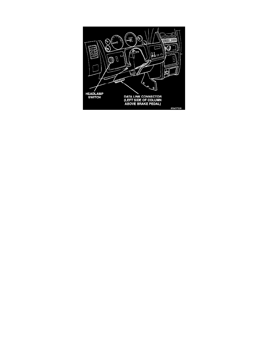
Fig. 14 DLC Location
The 16-way data link connector (diagnostic scan tool connector) links the Diagnostic Readout Box (DRB) scan tool or the Mopar Diagnostic
System (MDS) with the Powertrain Control Module (PCM). The data link connector is located under the instrument panel to the left of the
steering column (Fig. 14).
CIRCUIT OPERATION
Circuit A250 from fuse 11 in the Power Distribution Center (PDC) powers circuit F75 through fuse 7 in the junction block. Circuit F75 supplies
battery voltage to the data link connector.
Circuit D84 connects to cavity C29 of the PCM. Circuit D84 is the SCI transmit circuit for the Powertrain Control Module (PCM). Circuit D83
connects to cavity C27 of the PCM and cavity A3 of the Controller- Anti Lock Brakes. Circuit D83 is the SCI receive circuit for the PCM.
Circuits D83 and D98 from the speed proportional steering module connect to the data link connector.
Circuits Z1 and Z2 provide ground for the data link connector.