
Grand Cherokee 2WD L6-4.0L VIN S (1997)
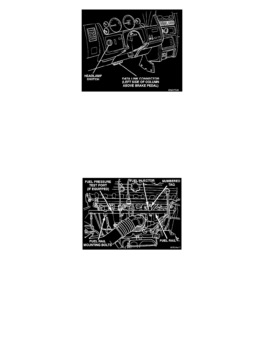
Fig. 14 DLC Location
The 16-way data link connector (diagnostic scan tool connector) links the Diagnostic Readout Box (DRB) scan tool or the Mopar Diagnostic
System (MDS) with the Powertrain Control Module (PCM). The data link connector is located under the instrument panel to the left of the
steering column.
Duty Cycle EVAP Purge Solenoid Valve
DUTY CYCLE EVAP PURGE SOLENOID VALVE-PCM OUTPUT
Refer to Emission Control Systems/Evaporative Emissions System/Canister Purge Solenoid/Description and Operation for information.
See: Emission Control Systems/Evaporative Emissions System/Canister Purge Solenoid/Description and Operation
Fuel Injectors
FUEL INJECTORS4.0L ENGINE-PCM OUTPUT
Fig. 16 Fuel Injectors
Six individual fuel injectors are used with this engine. The injectors are attached to the fuel rail.
The nozzle ends of the injectors are positioned into openings in the intake manifold just above the intake valve ports of the cylinder head. The
engine wiring harness connector for each fuel injector is equipped with an attached numerical tag (INJ 1, INJ 2 etc.). This is used to identify each
fuel injector.
The injectors are energized individually in a sequential order by the Powertrain Control Module (PCM). The PCM will adjust injector pulse width
by switching the ground path to each individual injector on and off. Injector pulse width is the period of time that the injector is energized. The
PCM will adjust injector pulse width based on various inputs it receives.
During start up, battery voltage is supplied to the injectors through the ASD relay. When the engine is operating, voltage is supplied by the
charging system. The PCM determines injector pulse width based on various inputs.