
Grand Cherokee 2WD L6-4.0L VIN S (1997)
relay location.
The Powertrain Control Module (PCM) activates the A/C compressor through the A/C clutch relay. The PCM regulates A/C compressor operation
by switching the ground circuit for the A/C clutch relay on and off.
When the PCM receives a request for A/C from A/C evaporator switch, it will adjust Idle Air Control (IAC) motor position. This is done to
increase idle speed. The PCM will then activate the A/C clutch through the A/C clutch relay. The PCM adjusts IAC stepper motor position to
compensate for increased engine load from the A/C compressor.
By switching the ground path for the relay on and off, the PCM is able to cycle the A/C compressor clutch. This is based on changes in engine
operating conditions. If, during A/C operation, the PCM senses abnormally low idle speeds it will de-energize the relay. This prevents A/C clutch
engagement. The relay will remain de-energized until the idle speed increases. The PCM will also de-energize the relay if coolant temperature
exceeds 125°C (257°F) or low or high system pressure exists.
Automatic Shutdown (ASD) Relay
AUTOMATIC SHUTDOWN (ASD) RELAY-PCM OUTPUT
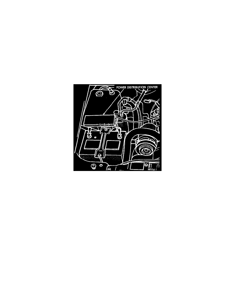
Fig. 13 PDC Location
The Automatic Shutdown (ASD) relay is located in the Power Distribution Center (PDC).
The ASD supplies battery voltage to the fuel injectors, ignition coil and both Oxygen (O2S) sensor heating elements. The ground circuit for the
coil in the ASD relay is controlled by the Powertrain Control Module (PCM). The PCM operates the relay by switching the ground circuit on and
off.
CCD Bus (+/-) Circuits
CCD BUS (+/-) CIRCUITS-PCM OUTPUTS
The Powertrain Control Module (PCM) sends certain output signals through the Chrysler Collision Detection (CCD) bus circuits. These signals
are used to control certain instrument panel located items and to determine certain identification numbers.
Data Link Connector
DATA LINK CONNECTOR-PCM INPUT AND OUTPUT