
Grand Cherokee 2WD L6-4.0L VIN S (1997)
Throttle Position Sensor: Description and Operation
THROTTLE POSITION SENSOR (TPS)-PCM INPUT
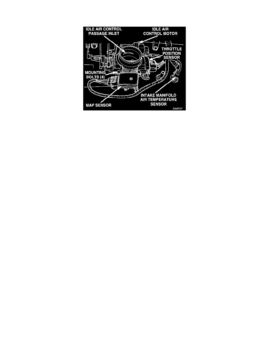
Fig. 9 Throttle Body & Sensors
The Throttle Position Sensor (TPS) is mounted on the throttle body (Fig. 9). The TPS is a variable resistor that provides the Powertrain Control
Module (PCM) with an input signal (voltage) that represents throttle blade position. The sensor is connected to the throttle blade shaft. As the
position of the throttle blade changes, the resistance of the TPS changes.
The PCM supplies approximately 5 volts to the TPS. The TPS output voltage (input signal to the PCM) represents the throttle blade position. The
PCM receives an input signal voltage from the TPS. This will vary in an approximate range of from 0.25 volts at minimum throttle opening (idle),
to 4.8 volts at wide open throttle. Along with inputs from other sensors, the PCM uses the TPS input to determine current engine operating
conditions. In response to engine operating conditions, the PCM will adjust fuel injector pulse width and ignition timing.
The Throttle Position Sensor (TPS) provides throttle position input signals to the Powertrain Control Module (PCM). This input signal is used to
determine overdrive and converter clutch shift schedule and to select the proper governor curve.
CIRCUIT OPERATION
From the Powertrain Control Module (PCM), circuit K25 supplies 5 Volts to the throttle position sensor (TPS). Circuit K25 connects to cavity
A17 of the PCM.
Circuit K22 delivers the TPS signal to the PCM. Circuit K22 connects to cavity A23 of the PCM.
The PCM provides a ground for the throttle position sensor signal (circuit K22) through circuit K4. Circuit K4 connects to cavity A4 of the PCM.