
Grand Cherokee 2WD V6-3.7L (2008)
Brake Light Switch: Description and Operation
Stop Lamp Inhibit Relay
Description
DESCRIPTION
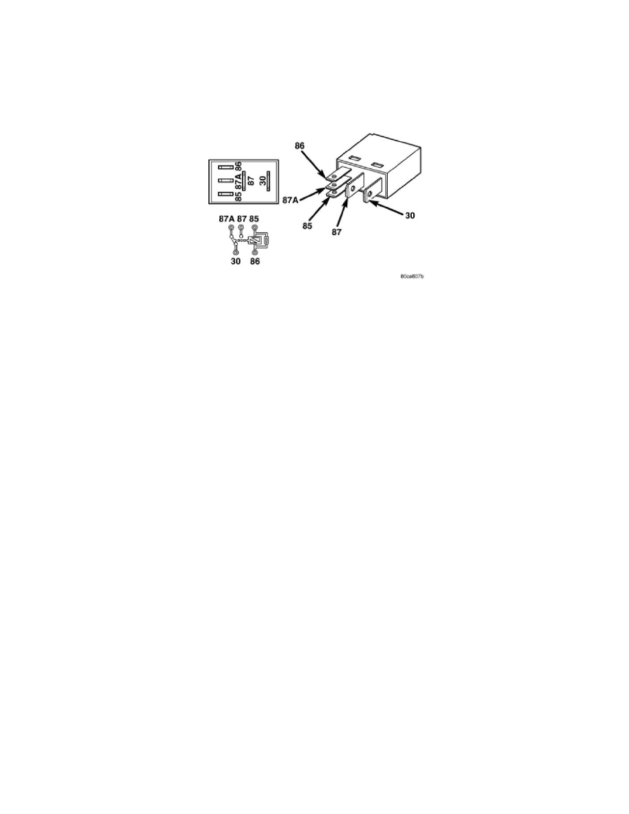
Vehicles equipped with an optional Electronic Stability Program (ESP)/Traction Control System (TCS) package have a stop lamp inhibit relay. The stop
lamp inhibit relay is a conventional International Standards Organization (ISO) micro relay. Relays conforming to the ISO specifications have common
physical dimensions, current capacities, terminal patterns, and terminal functions. The relay is contained within a small, rectangular, molded plastic
housing and is connected to all of the required inputs and outputs through five integral male spade-type terminals that extend from the relay base plate.
The stop lamp inhibit relay is located in the Junction Block (JB) in the passenger compartment under the driver side end of the instrument panel.
The stop lamp inhibit relay cannot be adjusted or repaired and, if ineffective or damaged, the unit must be replaced.
Operation
OPERATION
The stop lamp inhibit relay is an electromechanical switch that uses a low current input from the Controller Antilock Brake (CAB) to interrupt a high
current output from the brake lamp switch to the brake lamps. Within the relay is an electromagnetic coil, a movable contact and two fixed contact
points. A resistor is connected in parallel with the coil, and helps to dissipate voltage spikes and electromagnetic interference that can be generated as the
field of the relay coil collapses.
The movable common supply contact point is held against the fixed normally closed contact point by spring pressure. When the relay coil is energized,
an electromagnetic field is produced by the coil windings. This field draws the movable contact away from the normally closed contact, and holds it
against the normally open contact. When the relay coil is de-energized, spring pressure returns the movable contact back against the normally closed
contact.
The inputs and outputs of the stop lamp inhibit relay include:
-
Common Supply Terminal (30) - The common feed terminal is connected to the output of the brake lamp switch at all times.
-
Coil Ground Terminal (85) - The coil ground terminal is connected to a control output of the CAB through a stop lamp inhibit relay control
circuit. The CAB controls brake lamp operation by controlling a ground path through this circuit.
-
Coil Battery Terminal (86) - The coil battery terminal is connected to a fused ignition switch output (run-start) circuit at all times.
-
Normally Open Terminal (87) - The normally open terminal is not connected to any circuit in this application, but will have battery voltage
present whenever the relay is energized and the brake lamp switch is closed.
-
Normally Closed Terminal (87A) - The normally closed terminal is connected to the brake lamps through a brake lamp switch output circuit and
provides battery voltage to the brake lamps whenever the relay is de-energized.
The stop lamp inhibit relay as well as the hard wired inputs and outputs of the relay may be diagnosed using conventional diagnostic tools and
procedures. Refer to the appropriate wiring information.