
Grand Cherokee 2WD V8-4.7L Flex Fuel (2008)
Windshield Washer Pump: Description and Operation
Operation
Headlamp
HEADLAMP
Headlamp washer pump/motor unit operation is completely controlled by the Front Control Module (FCM) logic circuits based upon electronic wash
request and lighting request message inputs received from the ElectroMechanical Instrument Cluster (EMIC) (also known as the Cab Compartment
Node/CCN) over the Controller Area Network (CAN) data bus. The EMIC monitors electronic washer switch and lighting switch status messages
received over the Local Interface Network (LIN) data bus from the Steering Control Module (SCM). The SCM monitors analog and resistor multiplexed
inputs from the front washer switch circuitry contained within the right (wiper) multi-function switch and the exterior lighting switch circuitry of the left
(lighting) multi-function switch to determine the proper washer switch and lighting switch status messages to send.
The FCM will only allow the headlamp washers to operate when the ignition switch is in the ON position and the headlamps are turned ON. The BCM
uses high side drivers to energize or de-energize the headlamp washer system relay which, in turn, controls the operation of the headlamp washer
pump/motor unit.
The hard wired circuits and components of the headlamp washer pump/motor unit may be diagnosed using conventional diagnostic tools and procedures.
Refer to the appropriate wiring information. However, conventional diagnostic methods will not prove conclusive in the diagnosis of the headlamp
washer pump/motor or the electronic controls or communication between other modules and devices that provide some features of the headlamp washer
system. The most reliable, efficient, and accurate means to diagnose the headlamp washer pump/motor unit or the electronic controls and communication
related to headlamp washer pump/motor unit operation requires the use of a diagnostic scan tool. Refer to the appropriate diagnostic information.
Reversible
REVERSIBLE
The washer pump/motor unit features a reversible electric motor. The direction of the motor is controlled by hard wired outputs from the Front Control
Module (FCM). When battery current and ground are applied to the two pump motor terminals, the motor rotates in one direction. When the polarity of
these connections is reversed, the motor rotates in the opposite direction. When the pump motor is energized, the rotor-type pump pressurizes the washer
fluid and forces it through one of the two pump outlet nipples, and into the front or rear washer plumbing.
The FCM controls the hard wired outputs to the pump motor based upon electronic washer request messages received over the Controller Area
Network (CAN) data bus from the ElectroMechanical Instrument Cluster (EMIC) (also known as the Cab Compartment Node/CCN). The EMIC
monitors electronic washer switch status messages received over the Local Interface Network (LIN) data bus from the Steering Control Module (SCM).
The SCM monitors analog and resistor multiplexed inputs from the front and rear washer switch circuitry contained within the right (wiper)
multi-function switch to determine the proper washer switch status messages to send. Whenever the low washer fluid indicator is illuminated, the FCM is
programmed to suppress all rear washer requests in order to give priority to the need for forward visibility.
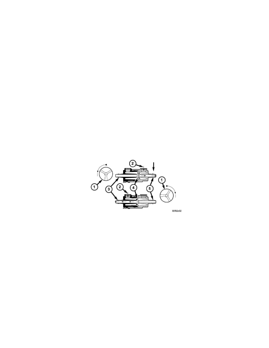
Washer fluid is gravity-fed from the washer reservoir to the inlet port of the washer pump housing. An integral valve body is located in a housing on the
outlet port side (2) of the pump housing. A diaphragm (4) in this valve body controls which washer system plumbing receives the washer fluid being
pressurized by the pump. When the pump is not operating the diaphragm is biased to close all washer fluid flow in the rear washer system and, in this
way it also performs the function of the rear washer system check valve.
When the pump impeller (1) rotates in the counterclockwise direction (viewed from the bottom), the biased diaphragm is sealing off the rear washer
system outlet and nipple so the pressurized washer fluid is pushed out through the pump front outlet port and the front washer outlet nipple (5). When the
pump impeller rotates in the clockwise direction (viewed from the bottom), pressurized washer fluid is pushed out through the pump rear outlet port and
moves the diaphragm to open the rear washer outlet nipple and seal off the front washer outlet nipple, then the pressurized washer fluid is pushed out
through the rear washer outlet nipple (3).
The washer pump/motor unit and the hard wired motor control circuits from the FCM may be diagnosed using conventional diagnostic tools and