
Grand Cherokee 2WD V8-4.7L VIN J (2004)
The alarm siren module consists of microprocessor, the siren, and a nickel metal hydride backup battery. All of the alarm module components are
protected and sealed within the housing.
The alarm siren module cannot be repaired or adjusted and, if faulty or damaged, it must be replaced.
The microprocessor within the alarm siren module provides the siren unit features and functions based upon internal programming and arm and
disarm messages received from the Intrusion Transceiver Module (ITM) over a dedicated serial bus communication circuit. The alarm siren
module will self-detect problems with its internal and external power supply and communication circuits, then send messages indicating the
problem to the ITM upon receiving a request from the ITM. The ITM will store a Diagnostic Trouble Code (DTC) for a detected alarm siren
module fault that can be retrieved with the DRB III scan tool over the Programmable Communications Interface (PCI) data bus.
When the premium version of the Vehicle Theft Alarm (VTA) is armed, the alarm siren module continuously monitors inputs from the ITM for
messages to sound its siren and enters its auto-detect mode. While in the auto-detect mode, if the alarm siren module detects that its power supply
or communication circuits are being tampered with or have been sabotaged, it will sound an alarm and continue to operate through its on-board
backup battery If the arm siren module is in its disarmed mode when its power supply or communication circuits are interrupted, the siren will not
sound. The alarm module will also notify the ITM when the backup battery requires charging, and the ITM will send a message that will allow the
backup battery to be charged through the battery voltage and ground circuits to the alarm module only when the ignition switch is in the ON
position and the engine is running. This will prevent the charging of the alarm backup battery from depleting the charge in the main vehicle battery
while the vehicle is not being operated.
The alarm siren module receives battery voltage through a fuse in the Power Distribution Center (PDC), and is grounded to the chassis. These
connections allow the alarm siren module to remain operational, regardless of the ignition switch position. The hard wired inputs and outputs for
the alarm siren module may be diagnosed and tested using conventional diagnostic tools and procedures. However, conventional diagnostic
methods will not prove conclusive in the diagnosis of the internal circuitry or the backup battery of the alarm siren module, the ITM, the serial bus
communication line, or the message inputs to and outputs from the alarm siren module. The most reliable, efficient, and accurate means to
diagnose the alarm siren module, the ITM, the serial bus communication line, and the electronic message inputs to and outputs from the alarm
siren module requires the use of a DRB III scan tool. Refer to the appropriate diagnostic information.
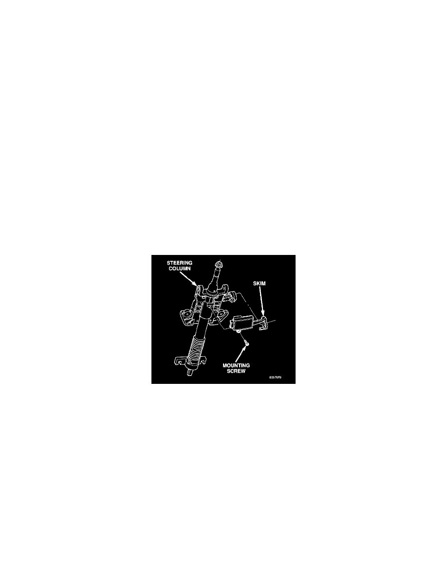
SENTRY KEY IMMOBILIZER MODULE
The Sentry Key Immobilizer Module (SKIM) is the primary component of the Sentry Key Immobilizer System (SKIS). The SKIM is located in
the steering column, below the ignition lock cylinder housing. The SKIM has an integral halo-like antenna ring that extends from one side.
The SKIM cannot be adjusted or repaired. If faulty or damaged, the entire SKIM unit must be replaced.
The Sentry Key Immobilizer Module (SKIM) contains a Radio Frequency (RF) transceiver and a microprocessor. The SKIM transmits RF signals
to, and receives RF signals from the Sentry Key transponder through a tuned antenna ring integral to the SKIM housing. If this antenna ring is not
mounted properly around the ignition lock cylinder housing, communication problems between the SKIM and the transponder may arise. These
communication problems will result in Sentry Key transponder-related faults. The SKIM also communicates over the Programmable
Communications Interface (PCI) data bus with the Powertrain Control Module (PCM), the ElectroMechanical Instrument Cluster (EMIC), the
Body Control Module (BCM), and/or the DRB III scan tool.
The SKIM retains in memory the ID numbers of any Sentry Key transponder that is programmed into it. A maximum of eight transponders can be
programmed into the SKIM. For added system security, each SKIM is programmed with a unique Secret Key code. This code is stored in memory,
sent over the PCI data bus to the PCM, and is encoded to the transponder of every Sentry Key that is programmed into the SKIM. Another security
code, called a PIN, is used to gain access to the SKIM Secured Access Mode. The Secured Access Mode is required during service to perform the
SKIS initialization and Sentry Key transponder programming procedures. The SKIM also stores the Vehicle Identification Number (VIN) in its
memory which it learns through a PCI data bus message from the PCM during SKIS initialization.