
Grand Cherokee 2WD V8-4.7L VIN J (2004)
Impact Sensor: Description and Operation
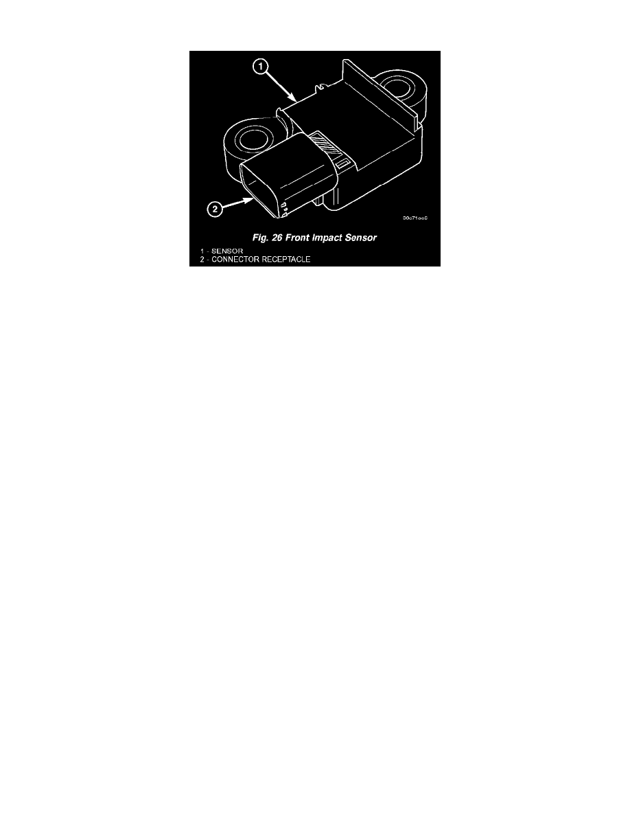
Fig. 26 Front Impact Sensor
FRONT IMPACT SENSOR
Two front impact sensors are used on this model, one each for the left and right sides of the vehicle. These sensors are mounted remotely from the
impact sensor that is internal to the Airbag Control Module (ACM). The right and left front and side impact sensors are identical in construction and
calibration with the exception of the right-hand and left-hand die cast aluminum mounting brackets to which each front impact sensor is secured with
two screws. The front impact sensor brackets are secured with three screws to the front and inboard sides of the right and left vertical members of the
radiator support within the engine compartment.
The impact sensor housing has an integral connector receptacle and two integral mounting ears, each with a metal sleeve to provide crush protection.
A cavity in the center of the molded black plastic impact sensor housing contains the electronic circuitry of the sensor which includes an electronic
communication chip and an electronic impact sensor. Potting material fills the cavity to seal and protect the internal electronic circuitry and
components. The front impact sensors are each connected to the vehicle electrical system through a dedicated take out and connector of the right or
left headlamp and dash wire harnesses.
The front impact sensors cannot be repaired or adjusted and, if damaged or faulty they must be replaced. If a front impact sensor is faulty, only the
sensor needs to be replaced. If the sensor or the sensor mounting bracket is damaged or faulty or if proper tightening torque of the screws that secure
the sensor to the bracket cannot be achieved, the sensor and bracket unit must be replaced.
The front impact sensors are electronic accelerometers that sense the rate of vehicle deceleration, which provides verification of the direction and
severity of an impact. Each sensor also contains an electronic communication chip that allows the unit to communicate the sensor status as well as
sensor fault information to the microprocessor in the Airbag Control Module (ACM). The ACM microprocessor continuously monitors all of the
passive restraint system electrical circuits to determine the system readiness. If the ACM detects a monitored system fault, it sets a Diagnostic Trouble
Code (DTC) and controls the airbag indicator operation accordingly.
The impact sensors each receive battery current and ground through dedicated left and right sensor plus and minus circuits from the ACM. The impact
sensors and the ACM communicate by modulating the voltage in the sensor plus circuit. The hard wired circuits between the front impact sensors and
the ACM may be diagnosed and tested using conventional diagnostic tools and procedures. However, conventional diagnostic methods will not prove
conclusive in the diagnosis of the ACM or the impact sensors. The most reliable, efficient, and accurate means to diagnose the impact sensors, the
ACM, and the electronic message communication between the sensors and the ACM requires the use of a DRBIII scan tool. Refer to the appropriate
diagnostic information.