
Grand Cherokee 2WD V8-4.7L VIN J (2004)
Remote Switch: Description and Operation
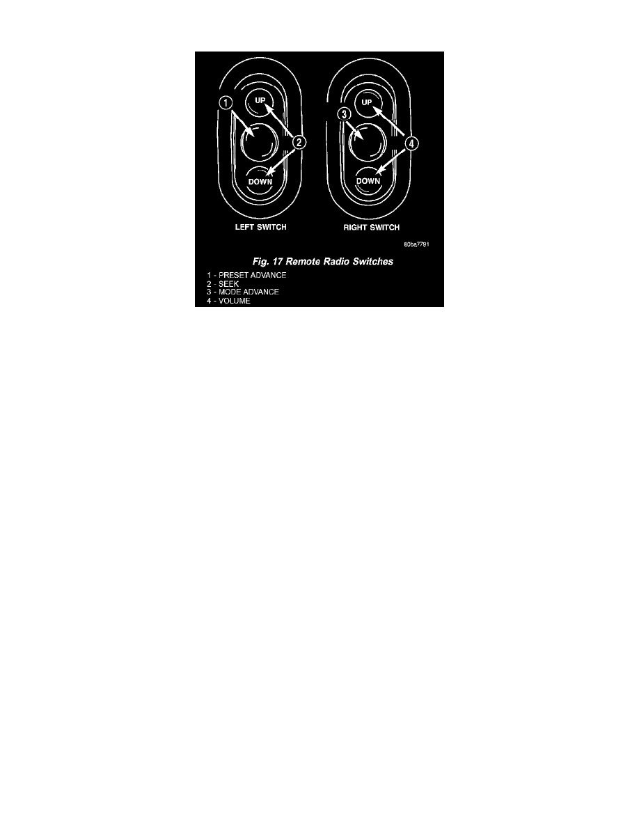
Fig. 17 Remote Radio Switches
REMOTE RADIO CONTROL SWITCHES
Remote radio control switches are included on models equipped with the optional leather-wrapped steering wheel. The two rocker-type switch units
are mounted in the upper spoke covers of the rear (instrument panel side) steering wheel trim cover. The switch unit on the left side is the seek switch
and has seek up, seek down, and preset station advance switch functions. The switch unit on the right side is the volume control switch and has volume
up, volume down, and mode advance switch functions.
The two remote radio switch units share a common steering wheel wire harness with the vehicle speed control switches. The steering wheel wire
harness is connected to the instrument panel wire harness through the clockspring.
For complete circuit diagrams, refer to the appropriate wiring information. The wiring information includes wiring diagrams, proper wire and
connector repair procedures, details of wire harness routing and retention, connector pin-out information and location views for the various wire
harness connectors, splices and grounds.
The six switches in the two remote radio switch units are normally open, resistor multiplexed momentary switches that are hard wired to the Body
Control Module (BCM) through the clockspring. The BCM sends a five volt reference signal to both switch units on one circuit, and senses the status
of all of the switches by reading the voltage drop on a second circuit.
When the BCM senses an input (voltage drop) from any one of the remote radio switches, it sends the proper switch status messages on the
Programmable Communication Interface (PCI) data bus network to the radio receiver. The electronic circuitry within the radio receiver is programmed
to respond to these remote radio switch status messages by adjusting the radio settings as requested. For diagnosis of the BCM or the PCI data bus, the
use of a DRB scan tool and the proper Diagnostic Procedures are recommended.
For more information on the features and control functions for each of the remote radio switches, see the vehicle glove box.