
Grand Cherokee 2WD V8-4.7L VIN J (2004)
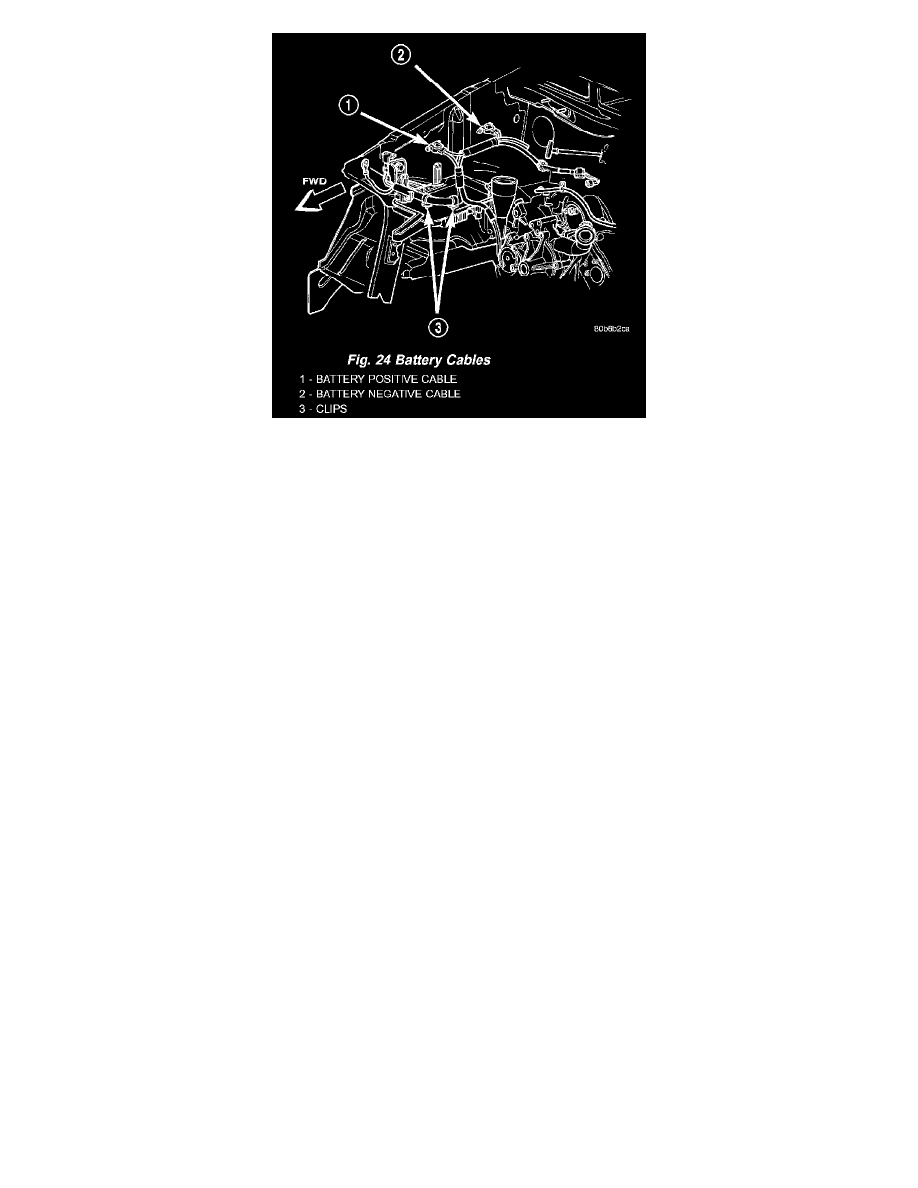
Fig.24 Battery Cables - 4.7L Engine
2. Position the battery wire harness into the engine compartment (Fig. 23) or (Fig. 24).
3. Reconnect the battery wire harness connector to the connector receptacle on the starter solenoid.
4. Install the battery positive cable eyelet terminal onto the B(+) terminal stud on the starter solenoid.
5. Install and tighten the nut that secures the battery positive cable eyelet terminal to the B(+) terminal stud on the starter solenoid. Tighten the nut to
11.3 Nm (100 in. lbs.).
6. Install and tighten the screw that secures the battery negative cable ground eyelet terminal to the right side of the engine block. Tighten the screw
to 10.2 Nm (90 in. lbs.) for 4.0L engines, or 13.0 Nm (115 in. lbs.) for 4.7L engines.
7. Reconnect the battery wire harness connector to the generator field terminal connector receptacle on the back of the generator.
8. Install the generator output cable eyelet terminal onto the generator output terminal stud.
9. Install and tighten the nut that secures the generator output cable eyelet terminal to the generator output terminal stud. Tighten the nut to 10.7 Nm
(95 in. lbs.).
10. Position the cover for the generator output terminal stud housing onto the back of the generator and snap it into place.
11. On models with the 4.7L engine, install the battery harness clip onto the stud on the right side of the intake manifold, then install and tighten the
nut that secures the clip to the stud. Tighten the nut to 11.3 Nm (100 in. lbs.).
12. Install and tighten the screw that secures the battery negative cable eyelet terminal to the inner fender shield near the front of the battery Tighten
the screw to 28.2 Nm (250 in. lbs.).
13. Reconnect the battery wire harness connector to the right headlamp and dash wire harness connector located near the front of the battery.
14. Install the battery positive cable and generator output cable eyelet terminal onto the PDC B(+) terminal studs.
15. Install and tighten the two nuts that secure the battery positive cable and generator output cable eyelet terminal to the PDC B(+) terminal studs.
Tighten the nuts to 11.3 Nm (100 in. lbs.).
16. Close and latch the PDC cover.
17. Reconnect the battery positive cable terminal clamp to the battery positive terminal post. Tighten the terminal clamp pinch-bolt hex nut to 6.8 Nm
(60 in. lbs.).
18. Reconnect the battery negative cable terminal clamp to the battery negative terminal post. Tighten the terminal clamp pinch-bolt hex nut to 6.8 Nm
(60 in. lbs.).
19. Apply a thin coating of petroleum jelly or chassis grease to the exposed surfaces of the battery cable terminal clamps and the battery terminal
posts.