
Grand Cherokee 2WD V8-4.7L VIN J (2004)
NOTE:
TO PREVENT ERROR, RE-COMPENSATE THE ALIGNER HEADS EACH TIME A CHANGE IS MADE TO A SETTING ON THE BALL
JOINT.
BALL JOINT INSTALLATION:
1.
Support the vehicle and front axle in a manner that will allow for the safe removal and installation of the respective upper ball joint(s).
2.
Remove the tire and wheel assembly.
3.
Remove the cotter pin, retainer, and nut used to secure the axle shaft to the wheel hub/bearing.
4.
Mark the brake rotor to the axle hub/bearing for later assembly. This step will help to minimize brake rotor lateral runout.
5.
Remove the two brake caliper slide pins. Remove the brake caliper, pads, and rotor.
6.
Properly support the brake caliper. Do not use the brake line to support the caliper.
7.
Remove the tie rod from the steering knuckle. Do not damage the boot.
8.
Mark the wheel hub/bearing to the steering knuckle for later assembly. This step will help to minimize brake rotor lateral runout.
9.
Remove the wheel hub/bearing and brake rotor shield. Carefully remove axle shaft.
10.
Remove the upper and lower ball joint cotter pins and nuts.
11.
Strike the steering knuckle with a brass hammer to loosen the steering knuckle from the ball joint. Lower the steering knuckle from the ball joints
studs.
12.
Remove the upper ball joint using the appropriate special tools from the # 6289 - Ball Joint Installation and Removal Kit.
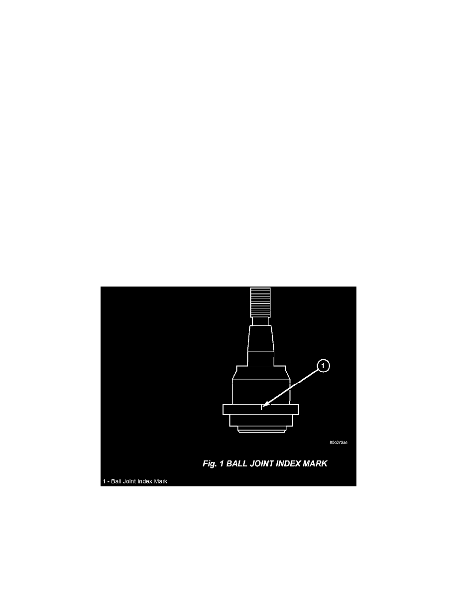
13.
A ball joint positioning template is supplied in the new offset ball joint package. In addition, an index mark is located on the side of the new offset
ball joint (Fig. 1). The ball joint index mark will be aligned to the respective mark on the template to obtain the desired angle.