
Grand Cherokee 2WD V8-4.7L VIN N (2000)
20.
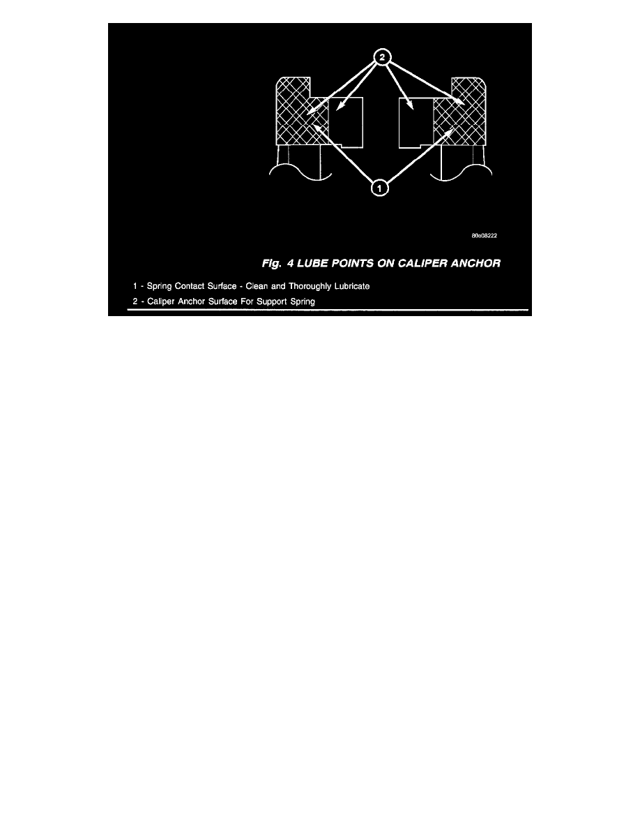
Coat the two support spring contact areas on the caliper anchor with Plastilube (Fig. 4).
21.
If an On-Car brake rotor lathe is available, install the original rotor to the hub/wheel bearing assembly. Align the rotor to the previously made
alignment (index) mark. Install a new rotor if an On-Car brake rotor lathe is not available. Match mount the hub/wheel bearing assembly to the
rotor. Refer to the appropriate Jeep Grand Cherokee Service Manual to achieve minimum rotor lateral run out.
NOTE:
THE LATERAL RUNOUT OF THE ROTOR WHEN IT IS SECURELY MOUNTED TO THE HUB/WHEEL BEARING ASSEMBLY SHOULD
NOT EXCEED 0.025 MM (0.001 IN.).
22.
If an On-Car brake rotor lathe is available, turn the rotor using the lathe manufacturers recommended procedures.
23.
Install the caliper anchor to the steering knuckle using new attaching bolts. Tighten the caliper anchor attaching bolts to 90-115 Nm (66-85 ft.
lbs.). Take care not to get Plastilube on the rotor.
24.
Carefully lubricate the caliper slide pins and slide pin bushings with the DC G807 (white color) grease that was provided in the kit. It is not
necessary to use all of the grease provided. Take care not to get grease on the brake pad linings or rotor.
25.
Install the caliper and slide pins. Tighten the slide pins to 29-41 Nm (21-30 ft. lbs.). Install the bushing caps.
26.
Install the new caliper support spring that was provided in the kit. There should be Plastilube where the support spring contacts with the caliper
anchor.
NOTE:
MOVE THE SUPPORT SPRING TO ITS NEUTRAL POSITION BY LIFTING EACH END OF THE SPRING (WHERE IT CONTACTS THE
ANCHOR) WITH A SCREWDRIVER AND RELEASING. BE CAREFUL TO NOT BIAS EITHER END OF THE SPRING TOO FAR
INBOARD OR OUTBOARD ALONG THE AXLE AXIS.
IF THE SPRING IS BIASED, ONE OR THE OTHER BRAKE PAD WILL TEND TO DRAG AGAINST THE ROTOR IN AN OFF-BRAKE
CONDITION.
27.
Install the wheel and tire assembly. Tighten the lug nuts to 135 Nm (100 ft. lbs.).
28.
Repeat the entire procedure for the other front brake assembly.
29.
Apply the brake pedal several times to advance the caliper pistons and until a firm brake pedal is obtained.
30.
Apply firm pressure to the brake pedal for 10 seconds to ensure proper final adhesion of the outer pad to the caliper fingers.
31.
Verify proper brake fluid level.