
Grand Cherokee 2WD V8-4.7L VIN N (2000)
Wiper Relay: Testing and Inspection
Wiper On/Off Relay Test
Wiper On/Off Relay
The wiper on/off relay is located in the Power Distribution Center (PDC) between the battery and the fender on the right side of the engine compartment.
See the fuse and relay layout label affixed to the inside surface of the PDC cover for wiper on/off relay identification and location.
1. Remove the wiper on/off relay from the PDC.
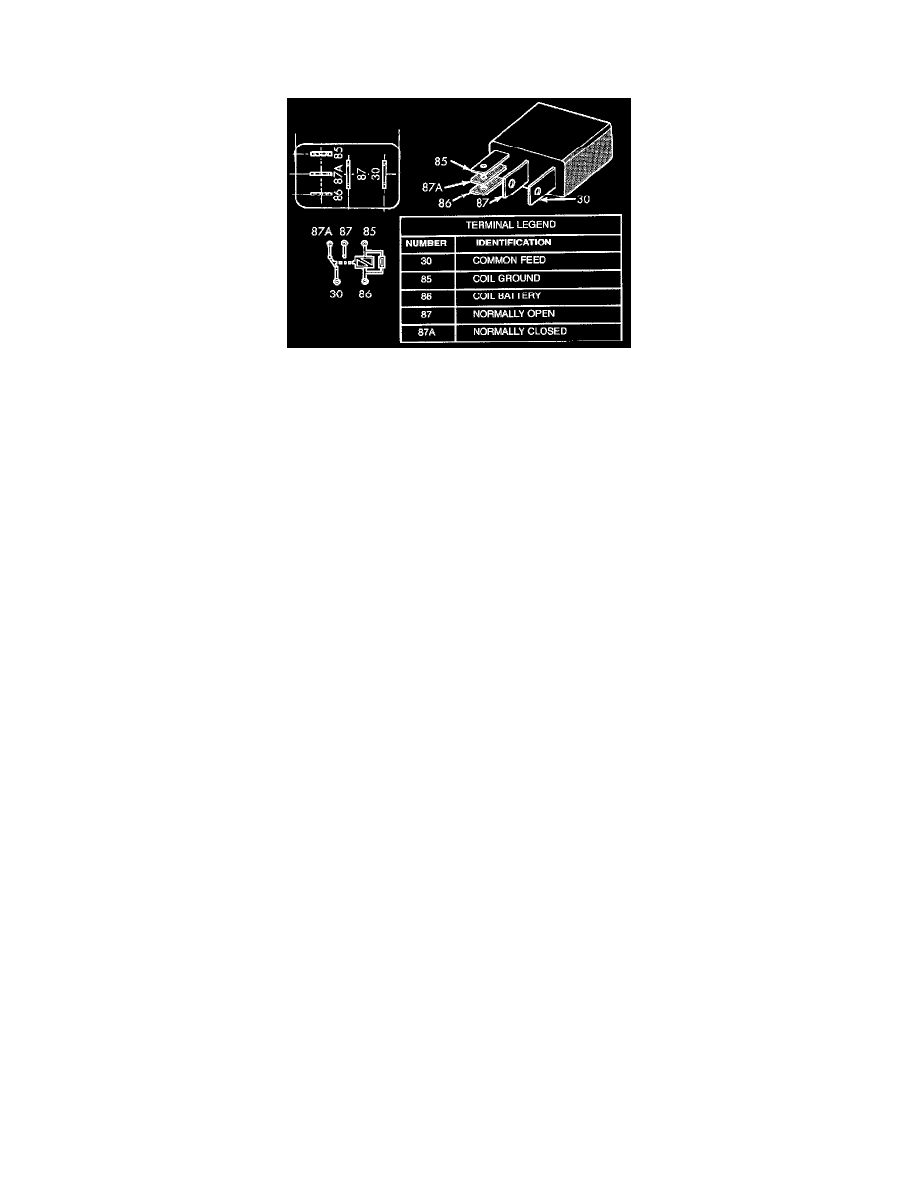
2. A relay in the de-energized position should have continuity between terminals 87A and 30, and no continuity between terminals 87 and 30. If OK,
go to Step 3. If not OK, replace the faulty relay.
3. Resistance between terminals 85 and 86 (electromagnet) should be 75 ± 5 ohms. If OK, go to Step 4. If not OK, replace the faulty relay.
4. Connect a battery to terminals 85 and 86. There should now be continuity between terminals 30 and 87, and no continuity between terminals 87A
and 30. If OK, perform the Relay Circuit Test that follows. If not OK, replace the faulty relay.
Relay Circuit Test
1. The relay common feed terminal cavity (30) is connected to the common feed terminal of the wiper high/low relay. When the wiper on/off relay is
de-energized, this terminal connects the wiper park switch sense circuit to the wiper high/low relay. When the wiper on/off relay is energized, this
terminal connects the fused ignition switch output from the wiper system circuit breaker to the wiper high/low relay. There should be continuity
between the cavity for terminal 30 of the wiper on/off relay and the cavity for terminal 30 of the wiper high/low relay at all times. If OK, go to
Step 2. If not OK, repair the open wiper on/off relay output circuit to the common feed terminal cavity for the wiper high/low relay in the PDC as
required.
2. The relay normally closed terminal (87A) is connected to the wiper park switch sense circuit. 'There should be continuity between the cavity for
terminal 87A of the wiper on/off relay and the wiper park switch sense circuit cavity of the windshield wiper motor connector at all times. If OK,
go to Step 3. If not OK, repair the open wiper park switch sense circuit to the windshield wiper motor as required.
3. The relay normally open terminal (87) is connected to the fused ignition switch output circuit. There should be battery voltage at the cavity for
terminal 87 of the wiper on/off relay when the ignition switch is in the On or Accessory positions. If OK, go to Step 4. If not OK, repair the open
fused ignition switch output circuit to the wiper system circuit breaker in the junction block as required.
4. The coil battery terminal (86) is also connected to the fused ignition switch output circuit. There should be battery voltage at the cavity for
terminal 86 of the wiper on/off relay when the ignition switch is in the On or Accessory positions. If OK, go to Step
5. If not OK, repair the open fused ignition switch output circuit to the wiper system circuit breaker in the junction block as required.
5. The coil ground terminal (85) is connected to the wiper on/off relay control circuit. It is grounded by the Body Control Module (BCM) to energize
the wiper on/off relay. There should be continuity between the cavity for terminal 85 of the wiper on/off relay and the wiper on/off relay control
circuit cavity of the 26-way instrument panel wire harness connector for the BCM at all times. If OK, use a DRB scan tool and the proper
Diagnostic Procedures to diagnose the BCM. If not OK, repair the open wiper on/off relay control circuit to the BCM as required.