
Grand Cherokee 2WD Limited V8-4.7L (2002)
Body Control Module: Description and Operation
Component Description
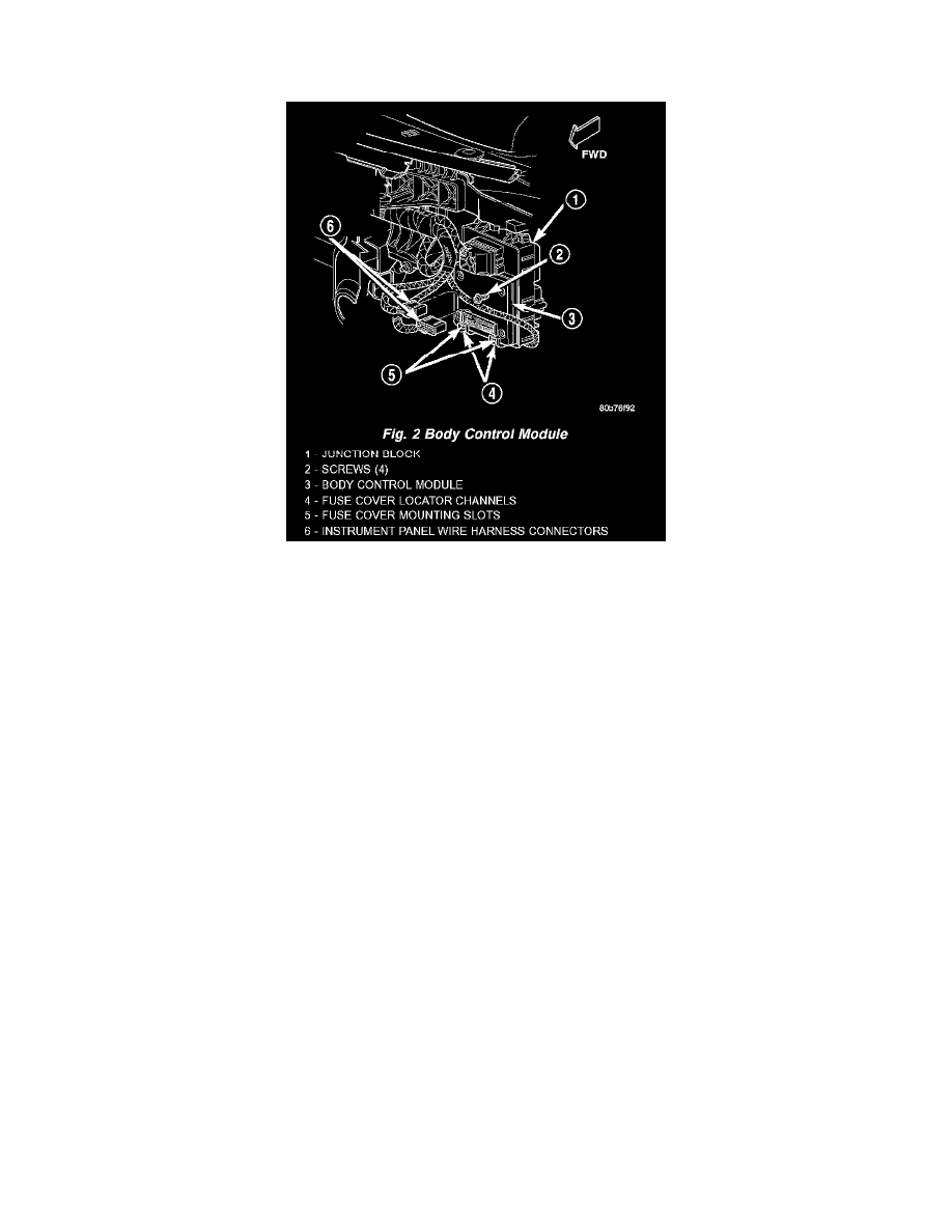
Fig.2 Body Control Module
BODY CONTROL MODULE
A Body Control Module (BCM) is concealed below the driver side end of the instrument panel.
The BCM utilizes integrated circuitry and information carried on the Programmable Communications Interface (PCI) data bus network along with
many hard wired inputs to monitor many sensor and switch inputs throughout the vehicle. In response to those inputs, the internal circuitry and
programming of the BCM allow it to control and integrate many electronic functions and features of the vehicle through both hard wired outputs and
the transmission of electronic message outputs to other electronic modules in the vehicle over the PCI data bus. The electronic functions and features
that the BCM supports or controls include the following:
The BCM for this model is serviced only as a complete unit. Many of the electronic features in the vehicle controlled or supported by the BCM are
programmable using either the Electronic Vehicle Information Center (EVIC) user interface, or the DRB III scan tool. In addition, the BCM software
is Flash compatible, which means it can be reprogrammed using Flash reprogramming procedures. A BCM can only be repaired by or replaced
through an authorized electronic warranty repair station. Refer to the latest version of the Warranty Policies and Procedures manual for a current
listing of authorized electronic repair stations.
The Body Control Module (BCM) is designed to control and integrate many of the electronic features and functions of the vehicle. The
microprocessor based BCM hardware and software monitors many hard wired switch and sensor inputs as well as those resources it shares with other
electronic modules in the vehicle through its communication over the PCI data bus network. The internal programming of the BCM microprocessor
allows the BCM to determine the tasks it needs to perform and their priorities. The BCM programming then performs those tasks and provides
features through both PCI data bus communication with other electronic modules and hard wired outputs to a number of relays. These relays provide
the BCM with the ability to control numerous high current accessory systems in the vehicle.
The BCM circuitry operates on battery current received through fuses in the Junction Block (JB) on a non-switched fused B(+) circuit, a fused
ignition switch output (start-run) circuit, and a fused ignition switch output (run-accessory) circuit. This arrangement allows the BCM to provide some
features regardless of the ignition switch position. The BCM circuitry is grounded through the chassis beneath the center console.
The BCM monitors its own internal circuitry as well as many of its input and output circuits, and will store a Diagnostic Trouble Code (DTC) in
electronic memory for any failure it detects. These DTCs can be retrieved and diagnosed using a DRB III scan tool. Refer to the appropriate
diagnostic information.
Hard Wired Inputs
The hard wired inputs to the BCM include the following:
-
A/C switch signal
-
Ambient temperature sensor signal