
Grand Cherokee 2WD Limited V8-4.7L (2002)
Clockspring Assembly / Spiral Cable: Description and Operation
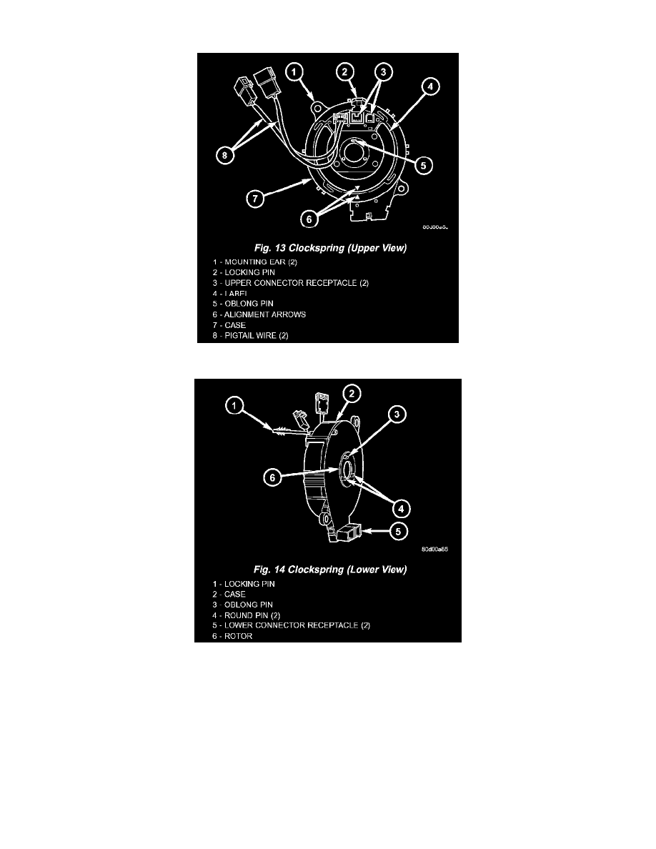
Fig.13 Clockspring (Upper View)
Fig.14 Clockspring (Lower View)
The clockspring assembly is secured with two screws to the multi-function switch mounting housing near the top of the steering column behind the
steering wheel. The clockspring consists of a flat, round molded plastic case with a stubby tail that hangs below the steering column and contains two
connector receptacles that face toward the instrument panel. Within the plastic housing is a spool-like molded plastic rotor with a large exposed hub. The
upper surface of the rotor hub has a large center hole, two large flats, an index hole, two short pigtail wires with connectors, and two connector
receptacles that face toward the steering wheel.
The lower surface of the rotor hub has three pins, two round and one oblong. These pins index the clockspring to the turn signal cancel cam unit in the
multi-function switch mounting housing. Within the plastic case and wound around the rotor spool is a long ribbon-like tape that consists of several thin
copper wire leads sandwiched between two thin plastic membranes. The outer end of the tape terminates at the connector receptacles that face the
instrument panel, while the inner end of the tape terminates at the pigtail wires and connector receptacles on the hub of the clockspring rotor that face the
steering wheel.