
Grand Cherokee 2WD Limited V8-4.7L (2002)
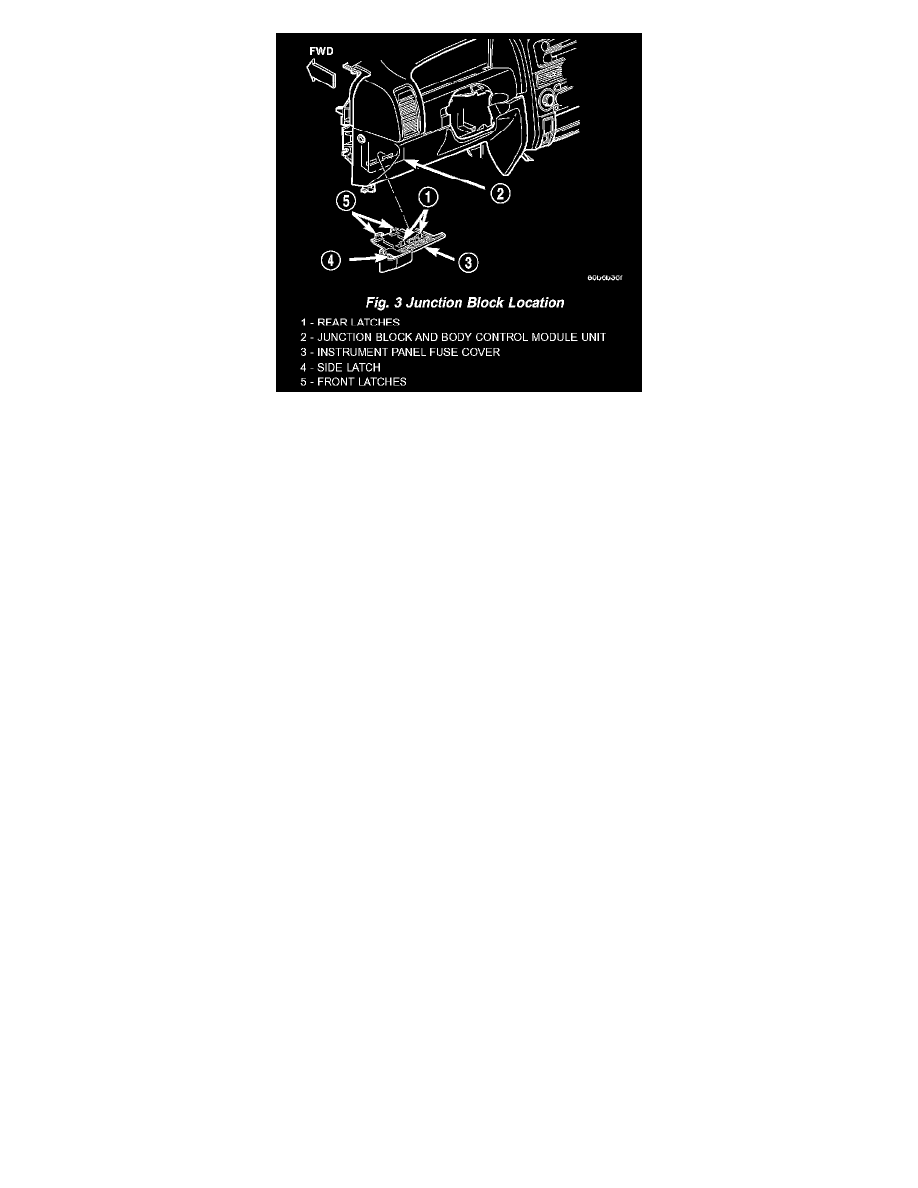
Fig.3 Junction Block Location
JUNCTION BLOCK
An electrical Junction Block (JB) is concealed beneath the driver side of the instrument panel in the passenger compartment of the vehicle (Fig. 3).
The JB combines the functions previously provided by a separate fuseblock module and relay center. The JB serves to simplify and centralize
numerous electrical components, as well as to distribute electrical current to many of the accessory systems in the vehicle. It also eliminates the
need for numerous splice connections. The JB houses up to thirty-three blade-type mini fuses, up to two blade-type automatic resetting circuit
breakers, the electronic combination flasher, the Daytime Running Lamp (DRL) module (Canada only) and up to twelve International Standards
Organization (ISO) relays (three standard-type and nine micro-type). The JB also incorporates an integral connector and mounting for the Body
Control Module (BCM). The BCM is secured with four screws directly to the dash panel side of the JB. Refer to Body Control Module in
Electronic Control Modules for additional information covering the BCM.
The molded plastic JB housing has integral mounts that are secured with two screws and two snap retainers to the instrument panel steering
column support bracket behind the instrument panel steering column opening cover. The JB is concealed above the molded plastic instrument
panel fuse cover. Integral latches molded into the fuse cover secure it the JB, the BCM and the 16-way data link connector tab of the instrument
panel steering column support bracket. The fuse cover can be pulled downward to disengage the latches and provide service access to all of the
fuses, relays and wire harness connectors of the JB. The fuse cover has a fuse puller and spare fuses secured to its upper surface. Refer to
Instrument Panel Fuse Cover in Body for additional service information.
The JB unit cannot be repaired and is only serviced as an assembly If any internal circuit or the JB housing is faulty or damaged, the entire JB unit
must be replaced. The BCM is available for separate service replacement.
All of the circuits entering and leaving the Junction Block (JB) do so through up to five wire harness connectors, which are connected to the JB
through integral connector receptacles molded into the JB housing. Internal connection of all of the JB circuits is accomplished by a printed circuit
board. There are also two separate wire harness connections to connector receptacles that are integral to the BCM. Refer to Junction Block in
Wiring Diagrams for additional information and the location of complete JB circuit diagrams.